


METIS M311 / M322 / H311 / H322 (17-pin)
SensorTools Software
39
dark offset by several degrees, this indicates the lens was not darkened 100% and ambient light
has penetrated. Then repeat the step.
-
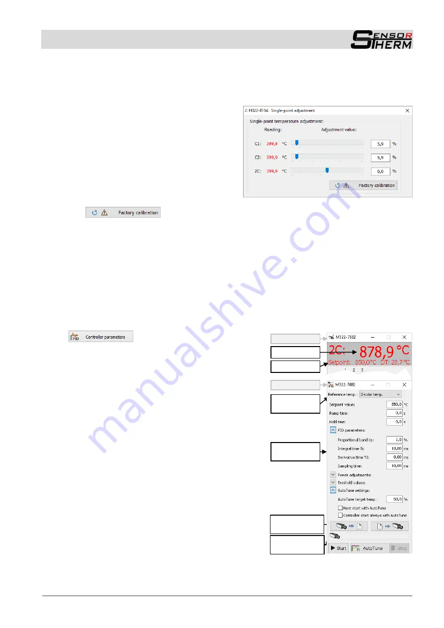
2C:
Finally, adjust the 2-color temperature until the temperature value of the calibration source
is shown correctly.
- H3 models:
- Move the sliders one by one for channel 1
(C1), channel 2 (C2) and finally for the ra-
tio temperature (2C) until the temperature
value of the calibration source is measured
correctly.
-
: The process takes between one and two minutes. If anything goes wrong,
for example the calibration source does not work smoothly, nevertheless calibration values are
written into the pyrometer. In this case the process should be performed again or the device should
be reset to factory settings, this sets all calibration values back to 0.0%.
7.2.4 PID Controller
M3 and H3 pyrometers with a 17-pin connector are equipped with an integrated PID controller. At this,
the temperature signal is converted into a control signal via a PID controller software. A setpoint value
and the necessary PID parameters are set to trigger a corresponding control value output. At the analog
output 2, the control signal is provided, via display and analog output 1 the current temperature reading
is available (factory setting, assignment can be changed in the pyrometer port settings, see
Parame-
ters / Settings
Device Settings and Configuration
).
An integrated PID controller is auto-
matically detected by the software and activates the button
for the controller configuration.
A setpoint and the necessary PID control parameters are
entered directly in the software and transferred to the py-
rometer by pressing the ENTER or tabulator key, control
parameters also can be changed during running control
mode. Invalid value entries are automatically corrected to
the next possible.
Control parameters:
Always visible parameters:
- Reference temperature:
selects the temperature
that is displayed in the control window (same function
as in the control window)
- Setpoint value:
Setpoint specification
- Ramp time
(in 100 ms)
:
The setpoint temperature
will be approached by increasing the temperature
with a uniform gradient of the temperature within the
entered time (the setpoint temperature in the grey
field above can show updated ramp temperatures if
the buffer mode settings in the data collection set-
tings (see
) are set to “with state information”).
- Hold time:
when reaching the desired value, the set-
point value in can be maintained at the current value.
The control process stops automatically after the hold
time is elapsed.
Start / Stop con-
trol process
Measured temp.
Setpoint display
Automatically find
control values
Setpoint specifi-
cation
Control parame-
ters
Control window
Controller window