Conquest 100
Assembling Conquest
18
3.1.2 Unpack the Components
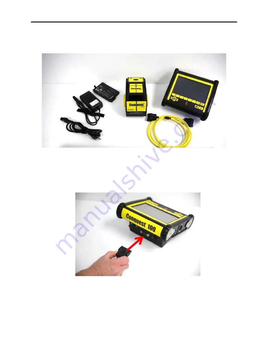
Remove all the system components and ensure all items are present (Figure 3-2).
Figure 3-2: Conquest 100 Base system components
3.1.3 Connect Cable to Display Unit
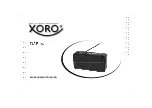
Connect the male end of the standard yellow sensor cable to the port on the back of the Display
Unit (Figure 3-3).
Ensure that the connection “clicks” into place so it cannot be disconnected
without squeezing the clips on either side of the connector.
Figure 3-3: Sensor cable connection to the Display Unit
3.1.4 Connect Cable to the Sensor Head
Connect the other (female) end of the yellow sensor cable to the Sensor Head in a similar
manner. Note that the receptacle is under the handle grip (Figure 3-4).
Display Unit
Sensor Head
Sensor
Cable
Battery
Battery Charger /
AC Adapter
AC Adapter
Cord
Summary of Contents for CONQUEST 100
Page 1: ... Copyright 2015 Sensors Software Inc 2015 00049 05 ...
Page 2: ......
Page 4: ......
Page 10: ......
Page 16: ...Conquest 100 Overview 6 ...
Page 46: ...Conquest 100 Main Screen 36 ...
Page 84: ...Conquest 100 Line Scan 74 ...
Page 104: ...Conquest 100 SliceView 94 ...
Page 114: ...Conquest 100 Transferring Data to a PC 104 ...
Page 116: ...Conquest 100 Transferring Data to a PC 106 ...
Page 120: ...Conquest 100 Troubleshooting 110 ...
Page 124: ...Conquest 100 Care and Maintenance 114 ...
Page 128: ...Conquest 100 Technical Specifications 118 ...
Page 130: ...Conquest 100 Appendix A Health Safety Certification A2 ...
Page 140: ...Conquest 100 Appendix C Instrument Interference C2 ...
Page 142: ...Conquest 100 Appendix D Safety Around Explosive Devices D1 ...


