SENSIRION SCD4 Series Manual Download Page 7


www.sensirion.com


Version 1.3 

 September 2022


7/24


3


Digital Interface Description 


All SCD4x commands and data are mapped to a 16-bit address space.  

SCD4x 

Hex. Code 

I

2

C address 

0x62 

Table 8 

I

2

C device address. 

3.1


Power-Up and Communication Start


The sensor starts powering-up after reaching the power-up threshold voltage V

DD,Min

 = 2.25 V. After reaching this threshold 

voltage, the sensor needs 1000 ms to enter the idle state. Once the idle state is entered it is ready to receive commands from 
the master. 

Each transmission sequence begins with a START condition (S) and ends with a STOP condition (P) as described in the I

2

C-

bus specification.  


3.2


Data type & length 

Data sent to and received from the sensor consists of a sequence of 16-bit commands and/or 16-bit words (each to be interpreted 

as unsigned integer, most significant byte transmitted first). Each data word is immediately succeeded by an 8-bit CRC. In write 

direction it is mandatory to transmit the checksum. In read direction it is up to the master to decide if it wants to process the 
checksum (see chapter 3.11)


3.3


Command Sequence Types


The  SCD4x  features  four  different  I

2

C  command  sequence  types: 

read  I

2

C  sequences

write  I

2

C  sequences

,“

send  I

2

command

 and 

send command and fetch result

 sequences. 

Figure 2

 illustrates how the I

2

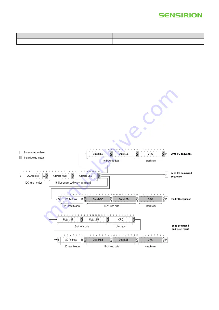
C communication for the different 

sequence types is built-up.   


Figure  2:

  Command  Sequence  types: 

write

  sequence, 

send

  command

  sequence, 

read


sequence, and 

send command and fetch result

 sequence. 

For 

read

” or 

“send command and fetch results”

 sequences, after writing the address and/or data to the sensor and sending the 

ACK bit, the sensor needs the 

execution time 

(se

Table 9

to respond to the I

2

C read header with an ACK bit. Hence, it is 

required to wait the command 

execution time 

before issuing the read header. Commands must not be sent while a previous 

command is being processed. 

Summary of Contents for SCD4 Series

Page 1: ...ns and CMOSens technology to offer high accuracy at an unmatched price and smallest form factor SMD assembly allows cost and space effective integration of the sensor combined with maximal freedom of...

Page 2: ...n 7 3 1 Power Up and Communication Start 7 3 2 Data type length 7 3 3 Command Sequence Types 7 3 4 SCD4x Command Overview 8 3 5 Basic Commands 9 3 6 On Chip Output Signal Compensation 10 3 7 Field Cal...

Page 3: ...e sensor specifications 1 Exposure to CO2 concentrations smaller than 400 ppm can affect the accuracy of the sensor if the automatic self calibration ASC is on 2 Deviation to a high precision referenc...

Page 4: ...sor performance and reliability of the device Parameter Conditions Value Temperature operating conditions 10 60 C Humidity operating conditions9 Non condensing 0 95 RH MSL Level 3 DC supply voltage 0...

Page 5: ...p which is adequately dimensioned for the relatively large peak currents Power supply configurations with large transient voltage drops are to be avoided to ensure proper sensor operation SCL is used...

Page 6: ...sensor readings The SCD4x supports the I2C standard mode as is described elsewhere see footnote 13 Parameter Condition Min Max Unit Power up time After hard reset VDD 2 25 V 1000 ms Soft reset time A...

Page 7: ...ansmitted first Each data word is immediately succeeded by an 8 bit CRC In write direction it is mandatory to transmit the checksum In read direction it is up to the master to decide if it wants to pr...

Page 8: ...write 1 no get_sensor_altitude 0x2322 read 1 no set_ambient_pressure 0xe000 write 1 yes Field calibration Chapter 3 7 perform_forced_recalibration 0x362f send command and fetch result 400 no set_auto...

Page 9: ...meter Max command duration ms length bytes signal conversion length bytes signal conversion 0x21b1 not applicable Example start periodic measurement Write 0x21b1 hexadecimal Command 3 5 2 read_measure...

Page 10: ...master sends one or several commands to get or set the sensor settings 3 If configurations shall be preserved after power cycle events the persist_settings command must be sent see chapter 3 9 1 4 The...

Page 11: ...etting see chapter 3 9 1 command must be issued Per default the sensor altitude is set to 0 meter above sea level Table 15 set_sensor_altitude I2C sequence description Write hexadecimal Input paramete...

Page 12: ...rifts originating from the sensor assembly process or other extensive stresses Automatic self calibration ASC ensures highest long term stability of the SCD4x without the need of manual action steps f...

Page 13: ...enabled To save the setting to the EEPROM the persist_setting see chapter 3 9 1 command must be issued Table 19 set_automatic_self_calibration_enabled I2C sequence description Write hexadecimal Input...

Page 14: ...periodic_measurement Description start low power periodic measurement signal update interval is approximately 30 seconds Table 21 start_low_power_periodic_measurement I2C sequence description Write he...

Page 15: ...t_settings I2C sequence description Write hexadecimal Input parameter Response parameter Max command duration ms length bytes signal conversion length bytes signal conversion 0x3615 800 Example persis...

Page 16: ...m_factory_reset command resets all configuration settings stored in the EEPROM and erases the FRC and ASC algorithm history Table 26 perform_factory_reset I2C sequence description Write hexadecimal In...

Page 17: ...d every 5 minutes Longer measurement intervals will result in less frequent self calibration sequences Note that no self calibration is issued if the sensor is power cycled between single shot measure...

Page 18: ...0 hexadecimal Command 3 10 4 wake_up Description Wake up the sensor from sleep mode into idle mode Note that the SCD4x does not acknowledge the wake_up command To verify that the sensor is in the idle...

Page 19: ...mple code C C Name CRC 8 define CRC8_POLYNOMIAL 0x31 define CRC8_INIT 0xFF uint8_t sensirion_common_generate_crc const uint8_t data uint16_t count uint16_t current_byte uint8_t crc CRC8_INIT uint8_t c...

Page 20: ...a b c d e f Nominal mm 10 1 10 1 8 5 7 8 5 5 0 8 Tolerance mm 0 3 0 3 0 2 0 2 0 3 0 2 Table 33 Nominal dimensions and tolerances SCD4x all in mm The weight of the sensor is approx 0 6 g Note that the...

Page 21: ...ent can result in yield loss and reliability degradation The manufacturing floor time out of bag at the customer s end is 168 hours at normal factory conditions 30 C and 60 RH If sensors are not mount...

Page 22: ...ys after the soldering process independently on whether the sensor is operated or not Average ramp up rate 3 C second Liquid phase TL tL 220 C 60 seconds Peak temperature TP tP 235 C 30 seconds Ramp d...

Page 23: ...t chapter 3 10 minor revisions on other pages May 2022 1 2 3 12 18 22 all Clarification on additional sensor accuracy drift Table 1 Clarification of set_ambient_pressure command description chapter 3...

Page 24: ...ired or replaced product shall be limited to the unexpired portion of the original period This warranty does not apply to any equipment which has not been installed and used within the specifications...

Reviews: