background image

Section 2—Data Types

Data Formats

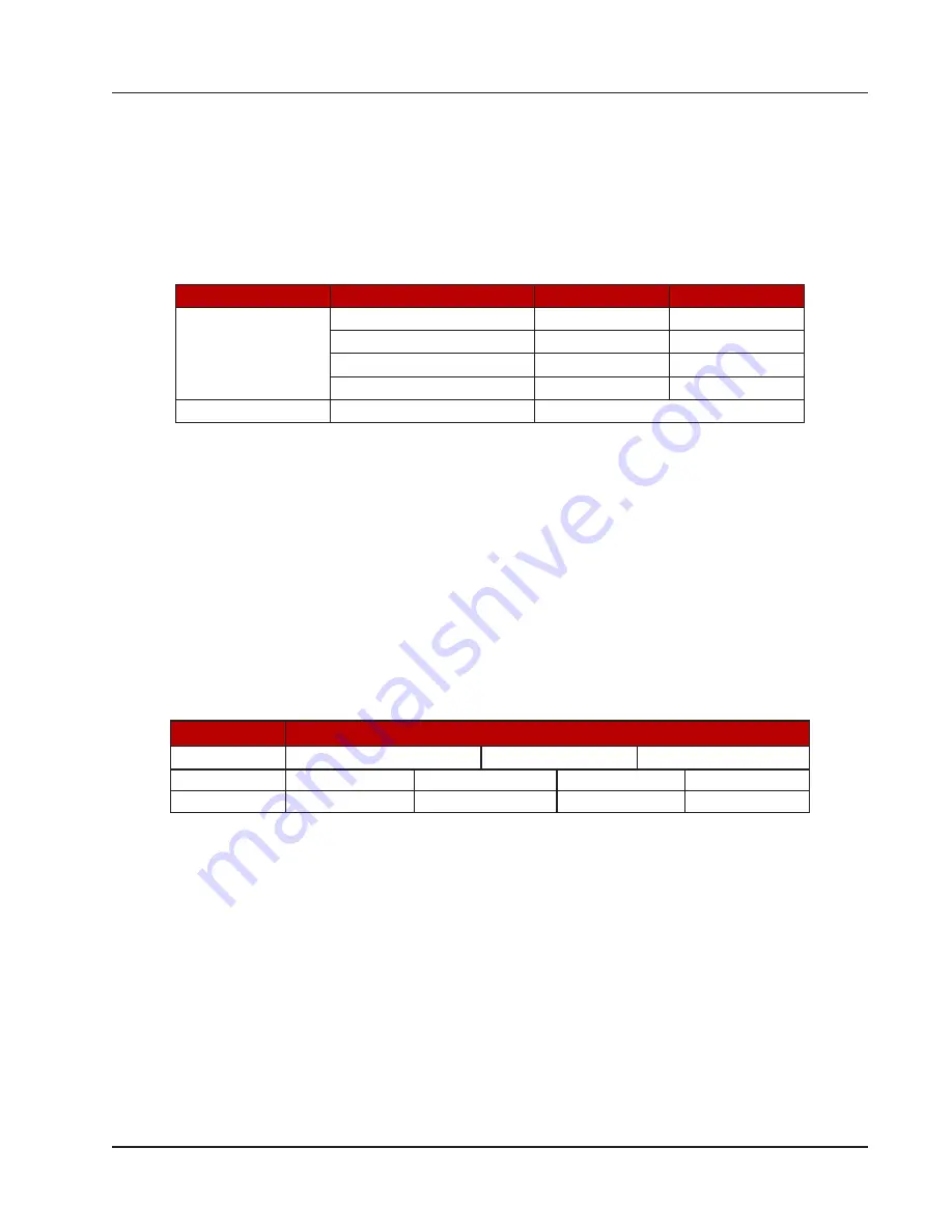
Various data types are implemented in the CamCor CT Series and PRO Series Coriolis meters. The following table lists 

the formats and the numbers of bytes and registers associated with each type.

Table 2.1—CamCor Data Formats

Data Format

Data Type

Byte Count

Register Count

16-bit

Floating Point (FP)

4

2

Unsigned Short Integer (U8)

2

1

Unsigned Integer (U16)

2

1

Unsigned Long Integer (U32)

4

2

Packed ASCII

Packed ASCII (PAC)

Se

Packed ASCII

 below

The word ordering for multiple register data types, such as floating-point numbers or long integers, places the most sig

-

nificant word first in the message. 

Unsigned Short Integer

The protocol for the CamCor Coriolis meters is based on a 16-bit data format. The value for “U8–Unsigned Short Inte

-

ger” is appended with 0x00. For example, if the value stored on the device is 125 (0x7D), the Standard Modbus Function 

Code 3 response is “0x007D.”

Packed ASCII

On CamCor meters, Packed ASCII uses three bytes to store four characters. For example, character string “ABCD” is 

stored as “0x0420C4” in Packed ASCII.

Table 2.2—CamCor Packed ASCII Code

Data Format

Data Appearance

Byte

0x04

0x20

0xC4

Bit

0  0  0  0  0  1

0  0  0  0  1  0

0  0  0  0  1  1

0  0  0  1  0  0

Character*

A(1)

B(2)

C(3)

D(4)

*The value inside parentheses is the Packed ASCII Code.

9

CamCor

 Modbus Protocol 

 Section 2

Summary of Contents for CamCor

Page 1: ...CamCor Modbus Protocol Manual Manual No 50284150 Rev 01 ...

Page 2: ...rocedures which may affect instrument operation or may lead to an instru ment response which is not planned Symbols Marked on Equipment Attention Refer to manual Protective earth ground Technical Support Contact Information Global headquarters Sensia LLC 200 Westlake Park Blvd Houston TX 77079 CamCor is a trademark of Sensia Modbus is a registered trademark of the Modbus Organization Inc All Right...

Page 3: ...Maps 11 Access Types 11 CamCor Specific Modbus Protocol Constraints 11 Updating Intervals 11 Modbus Registers 11 Device and System Information 11 Alarm Status Information 12 Communications Alarm Counter 12 Device Sensor and Slave Address Configuration 13 Damping Time Configuration 14 Output Configuration 14 Density Configuration 16 Alarm Status Configuration 16 Flow Configuration 17 Maintenance Co...

Page 4: ...This page is left blank intentionally iv Table of Contents CamCor Modbus Protocol ...

Page 5: ...to do so may cause er ratic and undesired responses from valves or other devices controlled by the system Consult Table 1 1 Communication Specifications below for CamCor Coriolis meter communication specifications Table 1 1 Communication Specifications Specification Description Communication System RS 485 Multidrop compliant Master Slave System Full duplex Half duplex Half duplex Baud Rate 9600 19...

Page 6: ...e the function code on the response message will be changed to the unexpected value code and 0x80 or 0x91 in this case original Function Code 80 The data value contains the exception code 0x02 Slave Addresses Allowed Slave Addresses Slave devices are shipped from the factory with a slave address of 1 Typically each slave device should be assigned a unique slave address Allowed slave addresses rang...

Page 7: ...s to all slave devices 1 Establish a point to point connection between the slave device and the CamCor meter 2 Send the following information Broadcast slave address 0 0x00 Function Code 16 0x10 Register 167 0x00A7 Data value to be written in this example Slave Address 1 0x0001 Data validity check CRC 0xB1FB The entire query string appears as follows 0x001000A70001B1FB Note The 0x prefix is used o...

Page 8: ...This page is left blank intentionally 8 Section 2 CamCor Modbus Protocol ...

Page 9: ... or long integers places the most sig nificant word first in the message Unsigned Short Integer The protocol for the CamCor Coriolis meters is based on a 16 bit data format The value for U8 Unsigned Short Inte ger is appended with 0x00 For example if the value stored on the device is 125 0x7D the Standard Modbus Function Code 3 response is 0x007D Packed ASCII On CamCor meters Packed ASCII uses thr...

Page 10: ...This page is left blank intentionally 10 Section 2 CamCor Modbus Protocol ...

Page 11: ...ster types separately will return a normal response but will not update the value displayed on the device Updating Intervals CamCor meters are synchronized to update Modbus readings every 1080 ms Sending a read query of less than 1080 ms may result in stale data since the reading will not be updated before the query is sent Therefore establish a read query time of greater than 1080 ms to ensure up...

Page 12: ...eration 1 Maintenace Mode RO 333 014D Resistance Connection U8 0 2 wires PRO Series 1 3 wires CT Series RO 334 014E Digital Signal Processing DSP Parameter Error U8 0 Normal 1 Error RO 335 014F Internal Communication Short Span Error U8 0 Normal 1 Communication Error RO 336 0150 LPO Overflow Status U8 0 Normal 1 Overflow RO 337 0151 RPO Overflow Status 338 0152 CPU Reset Status U8 0 More than 10 s...

Page 13: ...ge PAC 24 bytes 32 characters RW 22 0016 Tag Number PAC 6 bytes 8 characters RW 25 0019 Description PAC 12 bytes 16 characters RW 31 001F Day DD U8 1 31 RW 32 0020 Month MM U8 1 12 RW 33 0021 Year YY U8 00 99 RW 34 0022 Sensor Serial Number U32 0 1677215 RW 36 0024 Manufacture Number Sensor 92 005C Flange Type see Table 4 2 Flange Types and Sensor Materials U8 RO 93 005D Sensor Type Character Stri...

Page 14: ...og Output 2 Configuration 3 46 002E Analog Output Maximum Mass Flow Rate see Table 3 1 Configured Units page 16 then see Table 4 1 Units page 23 FP 9999999 to 9999999 RW 48 0030 Analog Output Minimum Mass Flow Rate RO 50 0032 Analog Output Maximum Volume Flow Rate RW 52 0034 Analog Output Minimum Volume Flow Rate RO 54 0036 Analog Output Maximum Density RW 56 0038 Analog Output Minimum Density RW ...

Page 15: ...e Count 0 FP 0 99999999 RW 120 0078 Pulse Output 2 Override Frequency Setting Hz 10000 FP 0 1 11000 0 RW 122 007A Pulse Output 2 Output Pulse Count 0 FP 0 99999999 RW 124 007C Flow 1 Total Control U8 1 Start 2 Stop 3 Reset RW 125 007D Flow 2 Total Control 126 007E Status Output Override U8 0 N C 1 N O 3 Stop RW 163 00A3 Pulse Output 1 Low Cutoff FP 0 0 10 0 165 00A5 Pulse Output 2 Low Cutoff 197 0...

Page 16: ... Decimal Register Hex Description Default Data Type Data Range Access 137 0089 Analog Output Error Setting 1 U8 0 Upscale 1 Downscale 2 Hold 3 Zero 4 mA RW 138 008A Pulse Output Error Setting 3 U8 0 Upscale 2 Hold 3 Zero 0 Hz RW 139 008B High Low Alarm Check Setting 0 U8 0 High Alarm Check 1 Low Alarm Check 2 High and Low Alarm Check RW 140 008C High Low Alarm Unit see Table 4 1 Units page 23 U8 R...

Page 17: ...ance Configuration Register Decimal Register Hex Description Default Data Type Data Range Access 206 00CE Maintenance Mode Disabled U8 RW 207 00CF Maintenance Mass Flow Rate Unit U8 RO 208 00D0 Maintenance Mass Flow Rate FP 9999999 to 9999999 RW 210 00D2 Maintenance Density see Table 3 1 Configured Units page 16 then see Table 4 1 Units page 23 FP 9999999 to 9999999 RW 212 00D4 Maintenance Inner T...

Page 18: ... 228 00E4 Mass Flow Rate Reading FP 230 00E6 Volume Flow Rate Unit U8 231 00E7 Volume Flow Rate Reading FP 233 00E9 Density Unit U8 234 00EA Density Reading FP 236 00EC Internal Temperature Unit U8 237 00ED Internal Temperature Reading FP 239 00EF Output Saturation Alarm see Table 3 2 Transmitter Status Data page 20 U8 RO 240 00F0 Sensor Failure Alarm 241 00F1 Transmitter Failure Alarm 242 00F2 Pa...

Page 19: ...t Input Amplitude U8 RO 291 0123 Self Diagnosis Result Input Temperature U8 RO 292 0124 Self Diagnosis Result Resistance Value U8 RO 293 0125 Self Diagnosis Result Static Installation Test U8 0 Best 1 Good 2 Fair 3 Poor RO 294 0126 Self Diagnosis Result Dynamic Installation Test U8 0 Stable Flow 1 Fairly Stable Flow 2 Unstable Flow RO 295 Reserved 296 0128 DSP Maintenance Remaining Time U8 30 to 0...

Page 20: ...ted 4 7 Reserved 240 Sensor Failure Alarm 0 Drive Input Out of Range 1 Scale Over 2 Temperature Out of Range 3 Density Outside Limits 4 P O Signal Error 5 Temp Connect Error 6 P O Connect Error 7 Reserved 241 Transmitter Failure Alarm 0 EEPROM Checksum Error 1 Data Update Error 2 Transmitter Interface Failure 0 3 Transmitter Interface Failure 1 4 Transmitter Interface Failure 2 5 Transmitter Inter...

Page 21: ...tput Fixed 5 0 Sig Lock 6 7 Reserved 247 Calibration in Progress 0 Calibration in Progress 1 Stability Check in Progress 2 7 Reserved 248 High Low Alarm 0 H L Alarm Triggered 1 7 Reserved 249 Maintenance in Progress 0 Key Volume Set in Progress 1 Self Diagnosis 2 Installation 3 Maintenance Test 4 Factory Data Operating 5 7 Reserved 250 Transmitter Operation 0 Transmitter Operating Time Over 1 Tran...

Page 22: ...This page is left blank intentionally 22 Section 3 CamCor Modbus Protocol ...

Page 23: ... 42 Imperial gal 81 lb min 31 gal day 43 m3 82 lb hr 130 ft3 hr 46 bbl 83 lb day 131 m3 min 112 ft3 84 U S short ton min 132 bbl sec 114 ml 85 short ton hr 133 bbl min 249 Special 86 short ton day 134 bbl hr Density 249 Special 135 bbl day CODE UNIT Temperature 138 L hr 90 SG CODE UNIT 139 ml sec 91 g cc 32 C 140 ml min 92 kg m3 33 F 141 ml hr 93 lb gal 34 R 240 L day 94 lb ft3 35 K 249 Special 95...

Page 24: ...4 50 50 2 3 67 C 19 83 S 68 68 51 51 3 4 68 D 20 84 T 36 36 52 52 4 5 69 E 21 85 U 37 37 53 53 5 6 70 F 22 86 V 38 38 54 54 6 7 71 G 23 87 W 39 39 55 55 7 8 72 H 24 88 X 40 40 56 56 8 9 73 I 25 89 Y 41 41 57 57 9 10 74 J 26 90 Z 42 42 58 58 11 75 K 27 91 43 43 59 59 12 76 L 28 92 44 44 60 60 13 77 M 29 93 45 45 61 61 14 78 N 30 94 46 46 62 62 15 79 O 31 95 _ 47 47 63 63 24 Section 4 CamCor Modbus ...

Page 25: ... s exclusive remedy in any case of action whether in contract tort breach of warranty or otherwise arising out of the sale or use of any products software supplies or materials is expressly limited to the replacement of such products software supplies or materials on their return to Seller or at Seller s option to the allowance to the customer of credit for the cost of such items In no event shall...

Reviews: