


72
CamCor CT and PRO Series Hardware Manual
Section 8
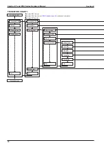
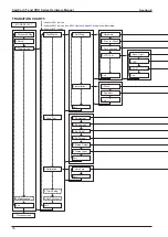
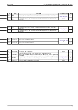
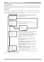
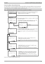
TRANSITION CHART 3
indicates SEL1 function
indicates SEL3 function (see
indicates ENT function
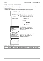
MODE SELECT
Process screen
1.Password & Disp
2.Setup
1.Flow Param
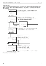
1.Ana. Output1
Exit
Exit
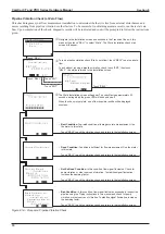
6.H/L Alarm
2.Ana. Output2
Exit
5.Status Input
4.Maintenance
3.Diag/Service
7.Error Output
6.Status Output
2.Den Param
3.Temp Param
4.Outputs
1.Assign
2.URV
3.LRV
4.Lowcut
5.Added Damp
Exit
1.Assign
2.URV
3.LRV
4.Lowcut
5.Added Damp
Exit
1.Assign
2.Freq Factor
3.Rate Factor
4.Lowcut
Exit
3.Pls. Output1
1.Assign
2.Pulse Weight
Exit
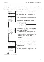
5.Pls. OpeMode
1.Assign
2.Freq Factor
3.Rate Factor
4.Lowcut
Exit
4.Pls. Output2
1.Assign
2.Pulse Weight
Exit
1.Weight
2.Frequency
Exit
Weight
Frequency
Weight
Frequency
Menu options
depend on Pulse
Operating Mode
selected.
Menu options
depend on Pulse
Operating Mode
selected.
Summary of Contents for CamCor CC001
Page 14: ...14 CamCor CT and PRO Series Hardware Manual Section 3 This page is left blank intentionally ...
Page 24: ...24 CamCor CT and PRO Series Hardware Manual Section 3 This page is left blank intentionally ...
Page 54: ...54 CamCor CT and PRO Series Hardware Manual Section 5 This page is left blank intentionally ...
Page 62: ...62 CamCor CT and PRO Series Hardware Manual Section 7 This page is left blank intentionally ...