A-6
CamCor CT and PRO Series Hardware Manual
Appendix A
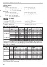
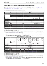
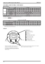
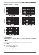
PRO SERIES SENSOR GENERAL PERFORMANCE
Mass Flow Rate
Item
Description
Model
CP006
CP010
CP015
CP025
CP040
CP050
Flow rate
Guaranteed minimum rate (kg/h)
24
76.8
192
576
1920
1920
Minimum setting rate (kg/h)
60
192
480
1440
4800
4800
Maximum service rate (kg/h)
600
1920
4800
14400
48000
48000
Maximum allowable rate (kg/h)
1200
3840
9600
28800
96000
96000
Uncertainty
±0.2% of reading (± zero stability)
Repeatability
±0.1% of reading (± 1/2 zero stability)
Zero stability (kg/h)
0.09
0.288
0.72
2.16
7.2
Density
(Liquid)
Metering range
0.3 to 2 g/mL
Uncertainty
±0.003 g/mL
Analog output uncertainty
±0.1% of full scale
Zero stability and flow rate during the test should read in the same measurement unit.
Zero stability error =
Zero stability
× 100%
Current flow rate
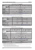
Volumetric Flow Rate
Item
Description
Model
CP006
CP010
CP015
CP025
CP040
CP050
Guaranteed minimum rate (l/min)
0.400
1.28
3.20
9.61
32.0
32.0
Minimum setting rate (l/min)
1.00
3.20
8.00
24.0
80.1
80.1
Maximum service rate (l/min)
10.0
32.0
80.0
240
801
801
Maximum allowable rate (l/min)
20.0
64.1
160
480
1601
1601
1. Calculations based on water (specific gravity of 1) at 15°C (mass = 999.13 kg/m
3
). Actual flow ranges vary with media density. To determine the flow range for your fluid,
divide the values above by the fluid’s specific gravity.
DISPLAY
lb/min
gal/min
Mass Flow
Vol Flow
CamCor
Coriolis Flow Meter
1. Mass instant flow rate
2. Volume instant flow rate
3. Density
4. Temperature
5. Pulse count 1 (mass or volume)
6. Pulse count 2 (mass or volume)
7. Total 1 (mass or volume)
8. Total 2 (mass or volume)
9. Analog 1 (% instant)
10. Analog 2 (% instant)
11. Status information
12. Mode select (parameter setup)
LED (Green)
LED (Red)
To select the mode, touch and hold your finger over the front glass
where the infrared optical sensor appears.
Display modes
• LCD backlight available in white and orange. Color
changes according to the status of flow meter.
• In most cases, the backlight shuts off automatically
if the optical sensor does not respond within a user-
defined duration.
Summary of Contents for CamCor CC001
Page 14: ...14 CamCor CT and PRO Series Hardware Manual Section 3 This page is left blank intentionally ...
Page 24: ...24 CamCor CT and PRO Series Hardware Manual Section 3 This page is left blank intentionally ...
Page 54: ...54 CamCor CT and PRO Series Hardware Manual Section 5 This page is left blank intentionally ...
Page 62: ...62 CamCor CT and PRO Series Hardware Manual Section 7 This page is left blank intentionally ...

