Page 12
12LPC15 Manual
DC Wire Gauge & Fusing Continued
Typical Cable Connection Procedure
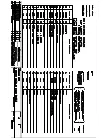
NOTE: Refer to Figure 4 for a typical DC wiring diagram. See Table 2 for proper cable sizes.
1.
Remove the fuse from the fuse holder.
2.
Connect the inverter’s bonding lug to ground of the vehicle chassis.
3.
Connect the ring terminated end of the black cable set and the temperature sensor cable directly to either the
negative (-) lead-acid battery post or to the positive (+) LFP battery post.
4.
Connect the fuse holder to the positive (+) side of the battery bank.
5.
Connect the ring terminated end of the red cable from the inverter to the fuse holder.
6.
Inverter DC connectors should be torqued to 160–165 inch-pounds.
7.
Install the fuse in the fuse holder. A typical one-time spark will occur when this final connection is made. Install
the fuse cover.
Figure 4 Typical DC Wiring Diagram