4
and then you should run an Ethernet cable from Data Input Port (on the
front of the Inline Power Injector) to the LAN connection (such as to a hub,
bridge or directly into a patch panel).
Step 4
Plug the MIL-C-5015 style Ethernet connector into the Special
Ethernet port on the back of the Router/Bridge.
Step 5
Plug the RJ-45 Ethernet connector (the other end of the Special
Ethernet cable) into the Power & Data Output Port on the front of the Inline
Power Injector.
Step 6
Attach the MIL-C-5015 style (RS-232) null modem cable to the
Serial Port Adapter. Connect the other cable end (DB9 female) to a terminal
or a PC running a terminal emulation program.
When the Router/Bridge receives power over the Ethernet cable, the
Router/Bridge will start its boot sequence and the Active LED on the front of
the Inline Power Injector will light up.
You can configure the Router/Bridge using the HTML browser, such as
Internet Explorer or Netscape Navigator from a remote host or PC.
NOTE:
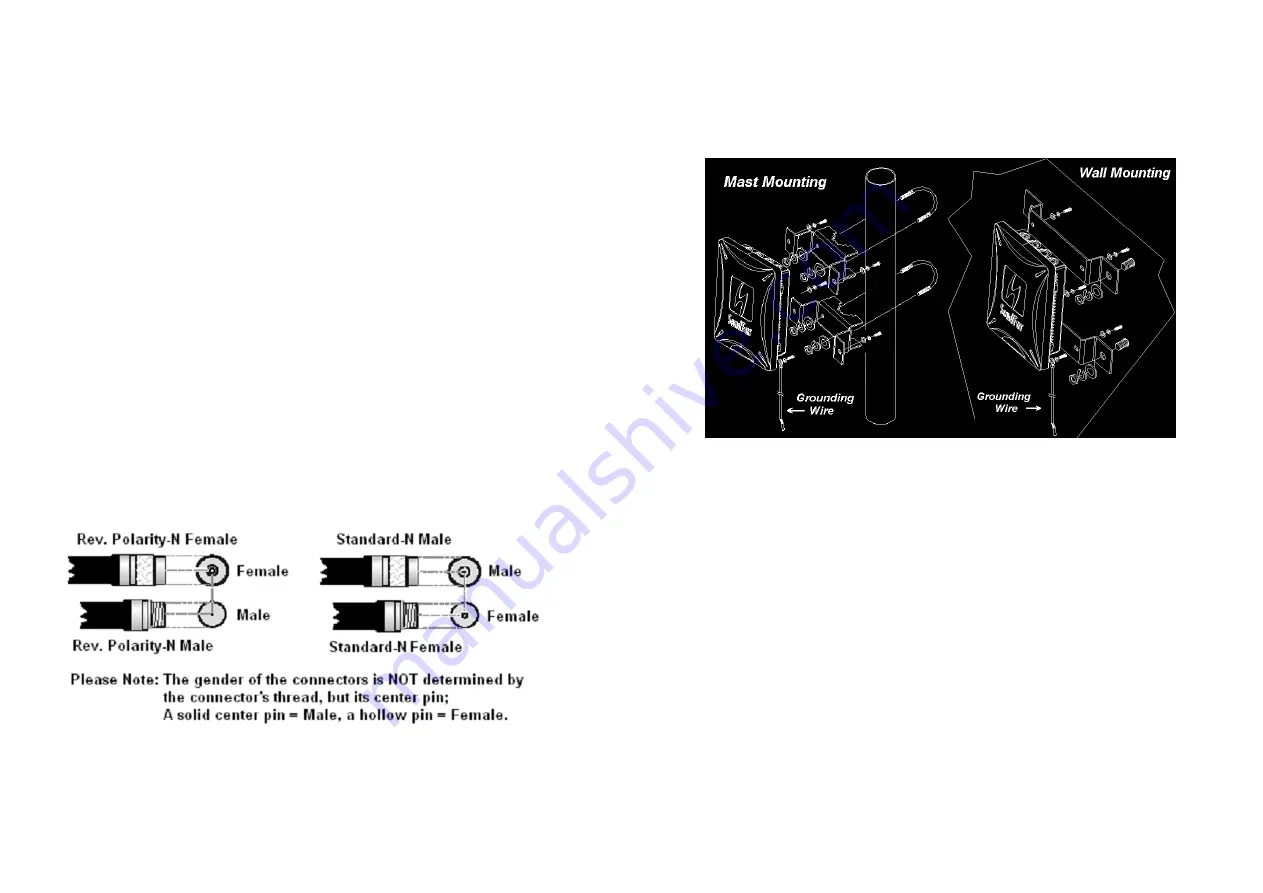
The outdoor Router/Bridge antenna cabling systems be identified by
Reverse Polarity-N connectors (pictured in following)
5
1.4 Outdoor
Installation
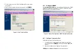
Outdoor Router/Bridge device can be mounted on the side of a
building or mounted to an antenna mast as shown in following:
A wall (side) mount allows for mounting an antenna (mast) on the side
of a building or on the side of an elevator penthouse. This will provide
a convenient mounting location when the roof overhang is not
excessive and/or the location is high enough to provide a clear line of
sight.
In most situations mounting an antenna directly to the wall will not
allow you to properly align the antenna with the corresponding
antenna at the opposite end of your wireless link. As poor alignment
will typically result in poor performance, we advise you to always
mount the Outdoor Router/Bridge and antenna to a mast.


