Revision 2.0 – July 2010
Page 22 of 24
www.semtech.com
© Semtech 2010
SX1231-31SKB
USER GUIDE
4. Click on the Transmitter radio button from within the Operating Mode Window and set the Repeat
value from within the Control Window of the Packet Handler Tab. It is recommended for initial
analysis that Repeat value is set to “0” (packet transmission repeat until manually stopped)
5. Click on the Start button within the Control Window of the Packet Handler Tab to start the
Transmitter
6. The TX packet counter will commence to increment as the SX1231 repeatedly transmits the
payload
7.1.2 Receiver Mode Configuration
1. Ensure that the SX1231 is in Standby operating Mode
2. Configure the SX1231 Common and Receiver Configuration Registers. The Common
configuration should be identical to that of the SX1231 configured as the transmitter. The
Receiver filter BW configuration should be consistent with the signal parameters. It is
recommended that the configuration of the transmitter module is used as a template
3. Configure the Packet Handler Registers for the payload you wish receive. Note that the packet
can be configured with Address and / or Broadcast nodes enabled or disabled; DC-free
mechanisms, CRC and / or AES may also be selected. The packet handler parameters must be
identical for those selected for the transmitter for correct operation. The only limitation is that he
maximum payload size for the purposes of GUI operation is 66 bytes
4. Click on the Receiver radio button from within the Operating Mode Window and set the Repeat
value from within the Control Window of the Packet Handler Tab
5. Click on the Start button within the Control Window of the Packet Handler Tab to start the
Receiver
6. The RX packet counter will commence to increment for each valid packet reception
7.2 Test Mode Window
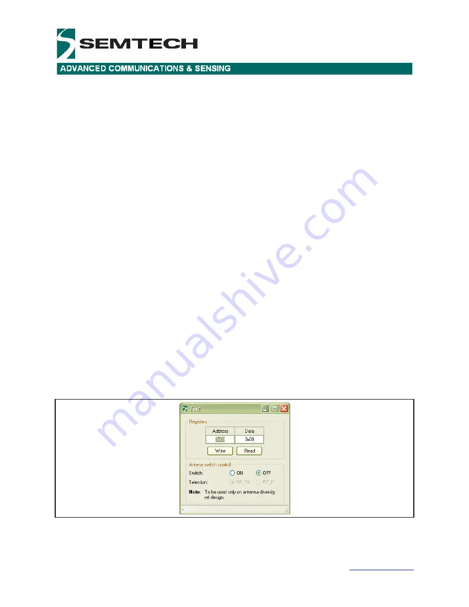
The Test Mode window is accessed by depressing the <CTRL>+<ALT>+<T> keys of the PC keyboard
simultaneously, and is illustrated below in Figure 27.
This window allows the user to write to and read from the contents of individual configuration register
addresses. Note that address and data are entered in hexadecimal format.
The Antenna switch control dialog box enables control of the antenna diversity switch for the SX1231
antenna diversity reference design
Figure 27: Test Mode Window


