


12
10-3/16"
11-3/16"
12-3/16"
14-3/8"
x
14-3/8"
6" 7"
8"
11-1/4"
12-1/4"
13-1/4"
A
B
A
B
Section
14-3/8"
x
14-3/8"
14-3/8"
x
14-3/8"
2
2.5
3
3.5
4
4.5
5
5.5
6
34
33
32
31
30
28
26
23
21
29
28.5
28
27
26
24
23
21
18
26
25.5
25
24
23
22
20
18
16
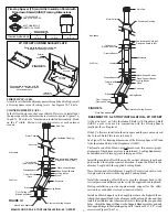
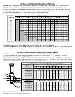
The following steps will assist you in the installation of the Wall
Thimble and of the Wall Support. Figure 11 shows a typical Wall
Support installation through a combustible wall.
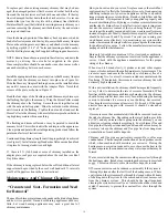
Distance
from Wall to
Chimney
6” ID
Chimney
7” ID
Chimney
8” ID
Chimney
H(feet)
Max. Height
H (feet)
Max. Height
H (feet)
Max. Height
D (inches)
Wall/Chimney
Table 2 - Wall Support
Chimney Height Chart
D
- Distance from wall to the chimney
H - Height of chimney in feet
See Figure 8 also.
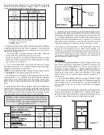
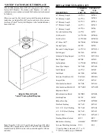
1. Determine the centre line of the horizontal connection (Chimney
Length through the wall) and frame an opening to the dimensions
specified for the Wall Thimble in a combustible wall (see Section A
in Table 3 and Figure 13-A).
- Use a stud finder to roughly locate the walls studs. Mark the
outline of the hole and drill a pilot hole in its center.
3. After framing in your opening to the dimensions specified to the
Framing Tables 1 or 3, install the outer half (with the unfinished
square plate) of the Wall Thimble into the outside wall opening.
Secure in place with appropriate fasteners through the pre-punched
holes.
2. For a non-combustible wall (concrete block or poured
foundation), cut a hole (3/16”) greater in diameter than the outside
diameter of the chimney as per Table 3.
NOTE:
When cutting the inside "finished" surface of your wall cut
a
"round hole"
to the framing dimension in Table 3.
- Break out part of the wall covering within the outline to confirm
that the hole will be centered between studs and that no electrical
wires could be cut by the saw.
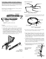
Wall Thimble
Black
Finishing
Round Plate
Interior Inner
Half of Wall
Thimble
Exterior Outer
Half of Wall
Thimble
Figure 12
Telescoping adjustment
from 4-1/2” to 8-3/4”
NOTE:
To reduce cold air infiltration into the dwelling you
can install the optional Universal Shielding Insulation (JUSI)
into the Wall Thimble. See separate installation instructions
packaged with the JUSI.
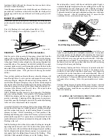
4. Install the inner half (with round plate) of the Wall Thimble into
the inside wall opening, ensuring that the shield slides over the shield
of the outer half. Once in place and flush against the wall, install the
black finishing trim plate onto the wall surface and fasten in place
with appropriate fasteners through the 4 pre-punched holes.
Two options are described below for the installation of the Wall
Support and the Insulated Tee assembly. Follow Method A if
inserting an assembled Insulated Chimney Length and Insulated Tee
into the Wall Thimble prior to the Wall Support. Follow Method B
if securing of the Wall Support to the wall prior to the Insulated Tee
and the Insulated Chimney Length.
METHOD A
6. Install an appropriate Insulated Chimney Length such as a one
foot section (or longer if required-not to exceed 24 inches) to the
horizontal branch of the Insulated Tee. Lock securely into the Tee
branch by twisting clockwise. A Locking Band must then be
installed to secure the connection. Make sure the nut and bolt are
facing down to prevent any water from collecting in the Locking
Band. The Tee branch extension must protrude a minimum of 3"
into the room.
5. Assemble the 2 side Brackets (point of triangle facing down) to
the Support Plate (flange up and threaded stud towards the wall) by
inserting the threaded studs into the oblong slots (see Figures 14 &
15). Install the supplied nuts on the threaded studs until snug, do not
tighten at this time as adjustments may be required. Set aside and
prepare the support bracing to secure the side brackets as per the
Framing Dimensions in Section B of Table 3 and Figure 13 (B).
7. From outside the building, slide the assembly (Chimney Length
installed on the Tee Branch) through the Wall Thimble ensuring the
male coupling on the Tee is facing upward. The Wall Thimble will
provide support until you are ready to install the Wall Support
Assembly.
8. Place the assembled Wall Support against the wall (Support Plate
Flange up) directly below the Insulated Tee. Slide the Wall Support
up to the bottom of the Insulated Tee ensuring that the flange on the
top of the Support Plate is inserted into the female coupler.
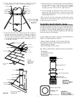
Table 3 -
Framing Dimensions Wall
Thimble & Support Brackets
Wall Thimble
Minimum Framed Opening
for Combustible Wall
Minimum Round Hole
Diam. For Non-Combustible Wall
Support Brackets
Minimum Framed Opening
For Bracing
Chimney Size (ID)
Figure 13


