background image

INSTRUCTION MANUAL     CODE 80303 REV B    

  Sep2019 

     (It can be modified without notice)           Page:  16

J

.P.  SELECTA s.a.u.      Autovía A-2 Km 585.1 Abrera  08630  (Barcelona) España   Tel 34 937 700 877   Fax 34 937 702 362

 e-mail: [email protected] - website:  http://www.jpselecta.es

7.3 Programming temperature profiles

A temperature profile is a sequence of steps defined by a temperature and a 

time. It also allows you to define a schedule for the start / end of the process.

The equipment allows defining up to 10 profiles of 6 steps each.

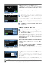
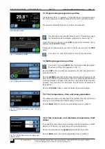
From the main screen, press this button to work in “Programming” mode; 

the temperature profile will appear graphically as shown in Fig 7.3.

To start the program, simply press the 

RUN

 key (the button will change its ap

-

pearance with the 

STOP

 message).

If during the program operation you wish to stop the process, press the 

STOP 

button.

From screen 7.3, click on this button to return to the main screen.

7.4 Editing temperature profiles 

From screen 7.3, press the 

EDIT

 button to select and modify the program. 

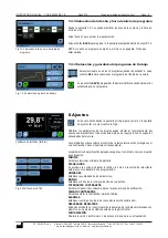
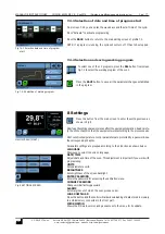
The screen will show the appearance of Fig. 7.4.

Press the 

EDIT

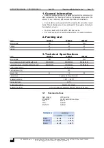
 button to modify the temperature, time and ramp parameters, 

as shown in Fig 7.4.1.

Press the 

ALARMS

 button to define the ranges between which the system should 

work. If the reading of the temperature is above or below the defined values, 

a warning message will appear telling that the programmed limits have been 

exceeded. These alarms are only informative, they do not stop the operation of 

the equipment.

Press the 

CYCLICAL

 button to repeat indefinitely the selected program.

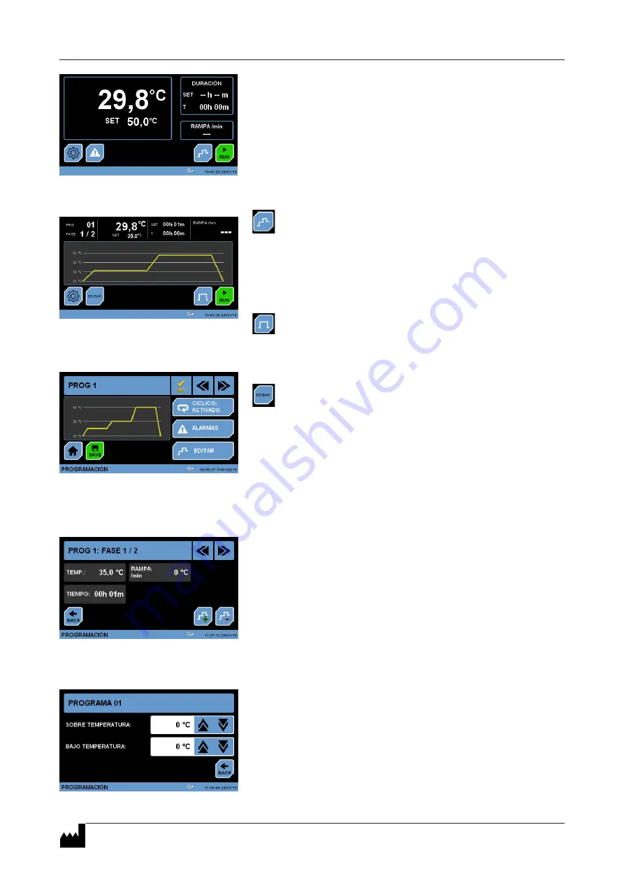
7.4.1 Set temperature, time and ramp parameters

The 

+ and - 

keys allow you to add steps to the profile and the left / right arrows 

allow you to move between the different phases of the profile.

Press the 

BACK 

button to return to the main editing screen of profile 7.4.

7.4.2 Set maximum and minimum temperature limit 

values

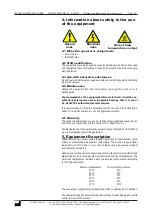
If you want the oven to show an alarm message when the temperature is outside 

margins, set a value for over temperature and for low temperature.

Press on the value and use the 

Up/Down 

keys to adjust these limits.

Press the 

BACK

 key to return to the main editing screen of profile 7.4.

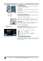
MAIN SCREEN (START)

Fig. 7.3 Temperature profiles

Fig. 7.4 Editing temperature profiles

Fig. 7.4.1 Modify temperature, ramp and time 

parameters.

Fig. 7.4.2 Modify maximum and minimum tem-

perature limits.

Summary of Contents for 2000963

Page 1: ...es sin previo aviso Pag 1 J P SELECTA s a u Autovía A 2 Km 585 1 Abrera 08630 Barcelona España Tel 34 937 700 877 Fax 34 937 702 362 e mail selecta jpselecta es website http www jpselecta es 2000963 36L 2000964 80L 2000965 150L Prebatem TFT Estufa de precisión Precision oven ...

Page 2: ...jpselecta es Indice 1 Información General 3 2 Lista de Embalaje 3 3 Especificación Técnica 3 4 Información sobre seguridad en la utilización del equipo 3 5 Descripción del equipo 4 6 Instalación 5 7 Funcionamiento 6 8 Ajustes 8 Index 1 General Information 12 2 Packing List 12 3 Technical Specifications 12 4 Information about safety in the use of the equipment 12 5 Equipment Description 13 6 Instal...

Page 3: ...60 0ºC Resolución del display 0 1ºC Funcionamiento temporizado Semanal hora minuto Perfiles de temperatura Hasta 10 perfiles de 6 segmentos Segmento de 1m a 99horas 3 1 Comunicaciones Conexión frontal Conector USB para descargar registros a memoria Conexiones posteriores ETHERNET Conexión puerto serie RS 232 DB9 Conexión puerto serie Micro USB 1 Información General Manipular el paquete con precauc...

Page 4: ...go de trabajo incluye la temperatura 20ºC que es muy útil para atemperar y preparar patrones de medida y calibración El sistema de calefacción y refrigeración se realiza mediante semiconduc tores y la regulación de la temperatura es electrónica con lectura digital Este sistema de refrigeración se ve afectado por la temperatura ambien te aumentando la temperatura mínima cuando aumenta la temperatur...

Page 5: ... conexión a tierra Antes de enchufar verificar que la tensión y frecuencia de la red eléctrica corresponde a la indicada en la etiqueta de características del equipo 6 3 Puesta en marcha incial Escoger una toma de corriente cercana al equipo y adecuada a la potencia del equipo Utilizar el cable de conexión suministrado u otro de similares ca racterísticas La estufa se pone en marcha con el interru...

Page 6: ... seleccionar la temperatura de trabajo Desde la PANTALLA PRINCIPAL pulsar encima del valor que se desea modificar El marco del parámetro modificable quedará recuadrado en amarillo En el ejemplo se puede modificar la temperatura Aparecen las teclas y que permiten incrementar disminuir el valor del ajuste Tras unos segundos sin pulsar ninguna tecla el marco amarillo desaparece y el valor ajustado qu...

Page 7: ...os de temperatura tiempo y rampa tal y como se muestra en la fig 7 4 1 Pulse el botón ALARMAS para definir los rangos entre los cuales debe trabajar el sistema Si la lectura de la temperatura está por encima o por debajo de los valores definidos aparecerá un mensaje de advertencia de que se ha sobrepa sado los límites programados Estas alarmas solo son informativas no detienen el funcionamiento de...

Page 8: ...antalla de ajustes tal y como muestra la Fig 8 Modificar los parámetros de los ajustes puede afectar al funcionamiento del equipo Lea atentamente todo el capítulo para que el equipo funcione según las necesidades del proceso Los parámetros más sensibles al control de la temperatura están protegidos por una contraseña Véase el capítulo correspondiente Los parámetros de ajuste están agrupados según ...

Page 9: ... tecla HOME para regresar a la pantalla inicial 8 3 Unidades Al entrar en este ajuste aparece la pantalla Fig 8 3 Utilice las flechas Arriba Abajo para seleccionar el parámetro del que desea cambiar la unidad La Fig 8 3 1 muestra la pantalla de selección de las unidades de la temperatura mediante las flechas Arriba Abajo se selecciona entre ºC y ºF Si se cambia este valor todos los valores mostrad...

Page 10: ... defecto para el calibrador es 0000 Pulse sobre el parámetro Offset de temperatura y con las teclas Arriba Abajo modifique este valor Pulse la tecla BACK para regresar al menú de ajustes o la tecla HOME para regresar a la pantalla inicial El valor de contraseña queda vigente hasta que la estufa se apague y encienda de nuevo Realice esta acción para evitar que otro usuario pueda modificar el valor ...

Page 11: ...l código ID DEVICE que aparece en la pantalla Fig 8 9 Cargue este fichero en una memoria USB e insértela en el conector frontal Atención durante el proceso de actualización NO apague el equipo ni extraiga la memoria USB del conector El equipo podría quedar sin control El proceso de actualización dura unos minutos durante el proceso de actualización el control se apaga varias veces pero esto es nor...

Page 12: ...rable part of the equipment and should be available to all users Check any doubt with J P SELECTA s technical service Do not use equipments in explosive flammable or corrosive atmospheres 2 Packing List Cooled low temperature incubator Prebatem TFT FORCED AIR FAN CIRCULATION MICROPROCESSOR CONTROLLED WITH DIGITAL DISPLAY ADJUSTABLE TEMPERATURES FROM 5 C UP TO 60 C RESOLUTION 0 1 C SEMICONDUCTOR HE...

Page 13: ...ized technical services It is recommended to clean the accessible parts of the oven with a cloth and a cleaner or a similar solution Do not use aggressive solvents 4 5 Warranty This product is guaranteed for one year It does not cover damages caused by an incorrect use or causes beyond the control of J P SELECTA s a u Any manipulation of the equipment by personnel not authorized by J P SELECTA s a...

Page 14: ...heck that the voltage and the frequency of the electrical supply corresponds to the one indicated on the label of the equipment 6 3 Starting Choose an electrical outlet near the equipment and appropriate for the equip ment power Use the supplied connection cable or a similar one The oven starts with the 0 I switch 2 It starts with the MAIN SCREEN Fig 6 3 1 RUN STOP buttons icons are activated acco...

Page 15: ... section 7 3 To select the working temperature From the MAIN SCREEN click on the value to be modified The frame of the modifiable parameter will be boxed in yellow In the example the temperature can be modified The and keys appear to increase decrease the value of the adjustment After a few seconds without pressing any key the yellow frame disappears and the adjusted value is selected The same ope...

Page 16: ...IT button to modify the temperature time and ramp parameters as shown in Fig 7 4 1 Press the ALARMS button to define the ranges between which the system should work If the reading of the temperature is above or below the defined values a warning message will appear telling that the programmed limits have been exceeded These alarms are only informative they do not stop the operation of the equipmen...

Page 17: ...ram 8 Settings Press this button from the main screen to enter the settings screen as shown in Fig 8 Modifying the settings parameters can affect the equipment operation Read carefu lly the entire chapter so that the equipment works according to the process needs Most sensitive temperature control parameters are protected by a password See the corresponding chapter Parameters settings are grouped ...

Page 18: ...ettings menu or the HOME key to return to the initial screen 8 3 Units When entering this setting screen Fig 8 3 appears Use the Up Down arrows to select the parameter from which you want to change the unit Fig 8 3 1 shows the screen for selecting the temperature units By using the Up Down arrows you select between ºC and ºF If this value is changed all displayed values will be referenced to this ...

Page 19: ...the CAL button The default password value for the calibrator is 0000 Press on the temperature Offset parameter and use the Up Down keys to modify this value Press the BACK key to return to the settings menu or the HOME key to return to the initial screen The password value remains valid until the oven is switched off and on again Perform this action to prevent another user from modifying the value...

Page 20: ...DEVICE ID code that appears in screen Fig 8 9 Load this file into a USB memory and insert it into the front connector Attention during the update process DO NOT turn off the equipment or remove the USB memory from the connector The equipment could run out of control The update process lasts a few minutes During the update process the control is turned off several times but this is normal Press the...

Reviews: