background image

Schweitzer Engineering Laboratories, Inc.

SEL-487B Data Sheet

9

Figure 16

Single SEL-487B Protecting Double Bus Sections With Bus Tie Breaker

Figure 17

Two Single SEL-487B Relays Protecting the Two Busbars in a Breaker-and-a-Half Busbar Configuration

For stations with 10 to 21 terminals (Figure 18), use
three separate SEL-487B relays and wire analog current
inputs from A-, B-, and C-phases separately into each
relay. This way, each of the 21 analog current inputs in
each relay measures only one phase, with six dedicated
zones of protection available. Each relay operates

independently; the only communication among relays is
M

IRRORED

  B

ITS

®

 communication and IRIG-B. In this

application, operators have complete flexibility because
they can close any disconnect at any time without
compromising the busbar protection. This is possible

Zone 1

Zone 2

52

52

52

52

52

3

3

3

3

3

3

400/5

FDR_1

FDR_2

FDR_3

FDR_4

800/5

2000/5

2000/5

4000/5

3000/5

SEL-487B

Bus 2

Bus 1

3

3
3

3

3
3

52

52

52

52

52

52

52

52

52

SEL-487B

SEL-487B

4000/5

2000/5

FDR_1

FDR_8

FDR_2

FDR_9

FDR_7

FDR_14

2000/5

1000/5

400/5

200/5

Summary of Contents for SEL-487B

Page 1: ...tem stability margins and reduce equipment damage Flexible zone selection and six differential zones provide protection for multiple busbar applications Failed CT detection elements reliably indicate...

Page 2: ...unctions in a Double Bus Application ANSI NUMBERS ACRONYMS AND FUNCTIONS 16 SEC Access Security Serial Ethernet 27 59 Over and Undervoltage 50 Overcurrent 50BF Breaker Failure Overcurrent 51 Time Over...

Page 3: ...lay for complex busbar arrangements The SEL 487B provides station wide protection through the use of up to six zones of differential protection advanced zone selection algorithms and per terminal brea...

Page 4: ...ration According to Disconnect Switch Positions Figure 4 Bus Arrangement With Disconnect DS2 Closed the New Zone 1 That Includes Bus Zones North and East ZONE Enter BUS PROTECTION Rinadel Station Term...

Page 5: ...tween an open circuit breaker and CT of a feeder at a substation This area is a dead zone because neither busbar protection nor local line protection can clear this fault the remote end of the feeder...

Page 6: ...estraint and operate current The advanced CT supervision in the SEL 487B monitors dif ferential zone restraint and operating current for these changes to provide rapid and dependable detection of open...

Page 7: ...g the close to open operation the 89b contact must close during the transition zone after the main contact arcing is extinguished disconnect is OPEN as shown in Figure 12 The 89a contact must open in...

Page 8: ...e CT as opposed to both main zones with an overlapping tie breaker arrangement Figure 15 Two CTs Configured With a Differential Element Across the Breaker Six Independent Settings Groups Increase Oper...

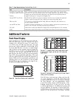
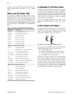
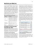
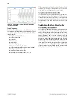
Page 9: ...current inputs in each relay measures only one phase with six dedicated zones of protection available Each relay operates independently the only communication among relays is MIRRORED BITS communicat...

Page 10: ...B Relays Protect Two Main Busbars and a Transfer Busbar Bus Coupler and 20 Terminals Optimize your SEL 487B by protecting both HV and LV busbars with three relays Figure 19 shows two HV busbars and tw...

Page 11: ...ct Both HV and LV Busbars Bus 1 Bus 2 52 400 5 400 5 800 5 400 5 800 5 800 5 52 52 52 52 Bus 3 Bus 4 52 400 5 400 5 800 5 4000 5 1600 5 52 52 400 5 52 52 FDR_1 FDR_4 TRFR_1 TRFR_2 FDR_2 FDR_12 FDR_3 3...

Page 12: ...c intervals the relay can be synchronized to an accuracy of 100 ns The relay is capable of receiving as many as 32 sync messages per second Figure 21 Example PTP Network SNTP Time Synchronization Use...

Page 13: ...perations e g trip settings group selection Replace traditional latching relays for such functions as remote control enable with 32 latching control points Program latch set and latch reset conditions...

Page 14: ...er settings you create offline by using a PC communications link with the SEL 487B The relay converts event reports to oscillograms with time coordinated element assertion and phasor diagrams The ACSE...

Page 15: ...transfers Choose Ethernet connection media options for primary and stand by connections 10 100BASE T Twisted Pair Network 100BASE FX Fiber Optic Network Communicate using IEC 61850 Logical Nodes and G...

Page 16: ...supports as many as seven simultaneous client associations Relevant Relay Word bits are available within the logical node data so you can use the IEC 61850 data server in the relay to monitor the stat...

Page 17: ...r programmable display points The rotating display scrolls through any active nonblank display points If none are active the relay scrolls through displays of the differential operating and restraint...

Page 18: ...following additional input output I O per interface board six independent inputs eighteen common inputs in two groups of nine six high speed high interrupting Form A outputs two standard Form A output...

Page 19: ...s of 1 kHz event data Relay settings operational in the relay at the time of the event display at the end of each filtered event report Use event report settings in the relay to assign up to 20 analog...

Page 20: ...Use this feature to gain a broad perspective of relay ele ment operation Items that trigger an SER entry are selectable and can include as many as 250 monitoring points such as input output change of...

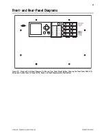
Page 21: ...487B Data Sheet 21 Front and Rear Panel Diagrams Figure 32 Standard Front Panel Diagram 9U Chassis Size Panel Mount Option Showing the Front Panel With LCD Navigation Pushbuttons 16 Target LEDs Reset...

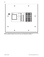
Page 22: ...eering Laboratories Inc 22 Figure 33 Expanded Front Panel Diagram 9U Chassis Size Panel Mount Option Showing Extended Front Panel HMI With LCD Navigation Pushbuttons 24 Tricolor LEDs Reset and 12 Prog...

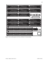
Page 23: ...Schweitzer Engineering Laboratories Inc SEL 487B Data Sheet 23 Figure 34 Rear Panel Diagram of the 9U Chassis With Four INT4 Interface Boards...

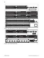
Page 24: ...SEL 487B Data Sheet Schweitzer Engineering Laboratories Inc 24 Figure 35 Rear Panel Diagram of the 7U Chassis With Two INT4 Interface Boards Figure 36 Rear Panel With EtherCAT Board...

Page 25: ...Schweitzer Engineering Laboratories Inc SEL 487B Data Sheet 25 Relay Dimensions Figure 37 Dimensions for Rack and Panel Mount Models...

Page 26: ...1 A Nominal 100 A 5 A Nominal 500 A One Cycle Thermal Rating Peak 1 A Nominal 250 A 5 A Nominal 1250 A Burden Rating 1 A Nominal 0 1 VA 1 A 5 A Nominal 0 5 VA 5 A AC Voltage Inputs Rated Voltage Range...

Page 27: ...Vdc 110 Vdc Pickup 88 0 132 0 Vdc Dropout 66 0 Vdc 125 Vdc Pickup 105 150 Vdc Dropout 75 Vdc 220 Vdc Pickup 176 264 Vdc Dropout 132 Vdc 250 Vdc Pickup 200 300 Vdc Dropout 150 Vdc AC Thresholds Ratings...

Page 28: ...WG 5 3 mm2 Electromagnetic Compatibility Immunity Conducted RF Immunity IEC 60255 22 6 2001 Severity Level 10 V rms IEC 61000 4 6 2008 Severity Level 10 V rms Electrostatic Discharge Immunity IEC 6025...

Page 29: ...nts 32 each remote bits local control bits latch bits in protection logic and latch bits in automation logic Relay Element Pickup Ranges and Accuracies Differential Elements Number of Zones 6 Number o...

Page 30: ...tting Range 0 99999 cycles 1 cycle step Breaker Status Monitor Number 21 Coupler Security Logic Number 4 Timer Setting Range 0 1000 cycles 1 12 cycle step Control Input Timers Setting Range Pickup 0 0...

Page 31: ...Schweitzer Engineering Laboratories Inc SEL 487B Data Sheet 31 Notes...

Page 32: ...nd international copyright and patent laws in its products including without lim itation software firmware and documentation The information in this document is provided for informational use only and...

Reviews: