SEL-487B Data Sheet
Schweitzer Engineering Laboratories, Inc.
6
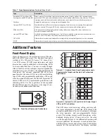
Figure 8
Differential Element Operation in Less Than
One Cycle for Internal Faults
Each of the differential elements provides the following:
➤
Fast operating times for all busbar faults
➤
Security for external faults with heavy CT satura-
tion
➤
Security with subsidence current present
➤
High sensitivity for busbar faults
➤
Minimum delay for faults evolving from external
to internal faults
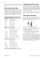
Figure 9 shows a block diagram of one of the six
differential protection elements.
Figure 9
External Fault Detection Logic Increases
Differential Element Security
CT saturation is one of the main factors to address when
considering relay security. Because of the high sampling
rate, the fault detection logic detects external faults in
less than 2 ms by comparing the rate of change of the
restraint and operating currents. Following the detection
of an external fault, the relay enters a high-security
mode, during which it dynamically selects a higher slope
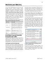
for the differential elements (see Figure 9). Figure 10
shows an external fault with heavy CT saturation,
without differential element operation.
Figure 10
Differential Element Does Not Operate for
External Fault With Heavy CT Saturation
CT Supervision
Open or shorted current transformers produce equal and
opposite changes in restraint and operate current. The
advanced CT supervision in the SEL-487B monitors dif-
ferential zone restraint and operating current for these
changes, to provide rapid and dependable detection of
open or shorted CT conditions. Use the CT supervision
logic in zone trip equations.
Voltage Elements
Voltage elements consist of two levels of phase under-
(27) and overvoltage (59) elements and two levels of
negative- (59Q) and zero-sequence (59N) overvoltage
elements, based on one set of three analog voltage quan-
tities. Table 2 provides a summary of the voltage ele-
ments.
Breaker Failure Protection
The SEL-487B includes complete breaker failure protec-
tion, including retrip, for each of the 21 terminals.
Because some applications require external breaker fail-
ure protection, set the SEL-487B to external breaker fail
and connect the input from any external breaker failure
relay to the SEL-487B; you can set any terminal to either
internal or external breaker failure protection.
Time (sec)
Cu
rr
ent (
Amp
s)
0
0.05
0.10
0.15
0.20
0
5
–5
0
0
5
10
15
20
Fault Inception
Internal
Fault Detection
(<1 cycle)
IO1
IO2
Fault
Detection Logic
Differential Element
Trip
Output
Internal
Fault
External Fault
CT
Supervision
Slope 1
Slope 2
Current
Input I01
Current
Input I18
IOP
IRT
Table 2
Voltage Elements
Element
Quantity
Levels
Undervoltage
Phase
Two levels
Overvoltage
Phase, negative-,
and zero-sequence
Two levels
–50
0
50
100
–150
0
–100
–50
0
50
Curr
ent (
Amp
s)
0.05
0.10
0.15
0.20
Time (sec)
(No Differential
Element Operation)
IO1
IO2
Internal
Fault Detection


