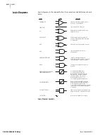


U.1.6
SEL-421/SEL-421-1 Relay
User’s Guide
Date Code 20020501
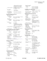
Introduction and Specifications
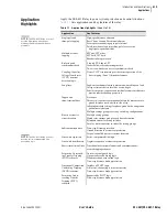
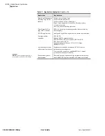
Applications
Applications
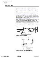
Use the SEL-421 Relay in a variety of transmission line protection
applications. For information on connecting the relay, see
Installation in the User’s Guide
. See
for thorough
discussions of protection and automation applications using the SEL-421
Relay.
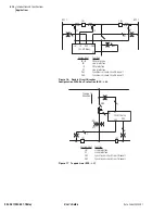
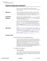
The figures in this subsection illustrate common relay application
configurations.
, and
demonstrate relay
versatility with Global setting ESS (Current and Voltage Source Selection).
These figures show the power and simplicity of the four preprogrammed ESS
options. For more information on setting ESS, see
Selection on page R.1.2 in the Reference Manual
.
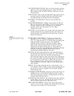
The SEL-421 Relay has two sets of three phase analog current inputs, IW and
IX, and two sets of three-phase analog voltage inputs, VY and VZ. The
drawings that follow use a two-letter acronym to represent all three phases of
a relay analog input. For example, IW represents IAW, IBW, and ICW for A-,
B-, and C-phase current inputs on terminal W, respectively. The drawings list
a separate phase designator if you need only one or two phases of the analog
input set (VAZ for the A-phase voltage of the VZ input set, for example).
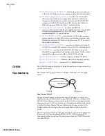
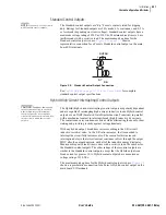
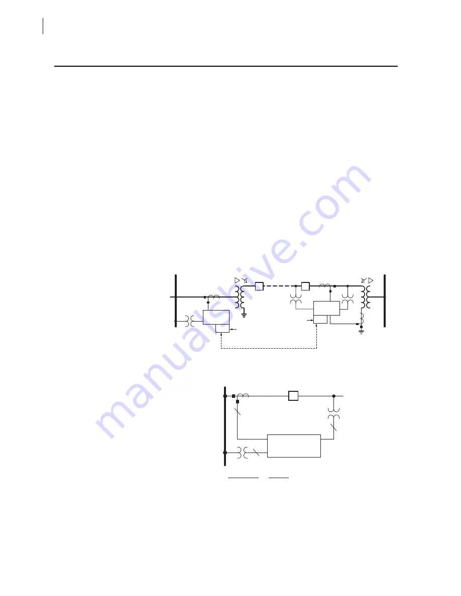
Figure 1.2
Protecting a Line Segment
With M
IRRORED
B
ITS
Communications on a Fiber Channel.
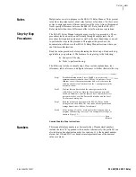
Figure 1.3
Single Circuit Breaker Configuration (ESS := 1).
SEL-421
Relay
CB
TX/RX
SEL-421
Relay
TX/RX
M
IRRORED
B
ITS
Communications
SEL-28XX
SEL-28XX
BUS 1
BUS 2
CB
SEL-421 Relay
BUS
CB1
3
3
IW
VAZ
VY
1
Analog Input
IW
VY
VAZ
Function
CB1 protection, line protection
Line protection
Synchronism check
Summary of Contents for SEL-421
Page 8: ...This page intentionally left blank ...
Page 30: ...This page intentionally left blank ...
Page 110: ...This page intentionally left blank ...
Page 204: ...This page intentionally left blank ...
Page 284: ...This page intentionally left blank ...


