


4.90
SEL-751A Relay
Instruction Manual
Date Code 20100129
Protection and Logic Functions
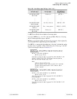
Logic Settings (SET L Command)
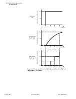
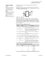
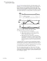
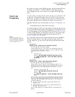
shows an example of the effects of the input precedence, with
SC01PV set to 7. The vertical dashed line indicates the relationship between
SC01CU first being seen as a rising edge and the resultant outputs. This
indicates that there is no intentional lag between the control input asserting
and the count value changing. Most of the pulses in the diagram are on every
second processing interval. The “one processing interval” valley is an example
where the CD and CU pulses are only separated by one processing interval.
Figure 4.49
Example of the Effects of the Input Precedence
The shaded areas illustrate the precedence of the inputs:
➤
When SC01R is asserted, the SC01LD input is ignored.
➤
When SC01R or SC01LD is asserted, rising edges on the
SC01CU or SC01CD inputs are ignored.
➤
When input SC01CU has a rising edge, a rising edge on
SC01CD is ignored (unless SC01 is already at the maximum
value SC01PV (= 7), in which case SC01CU is ignored, and the
SC01CD is processed). An example of this exception appears
in the above diagram, just before the “one processing interval”
notation.
A maintained logical 1 state on the SC01CU or SC01CD inputs is ignored
(after the rising edge is processed). A rising edge received on the SC01CU or
SC01CD inputs is ignored when the SC01R or SC01LD inputs are asserted.
A maintained logical 1 on the SC01CU or SC01CD inputs does not get treated
as a rising edge when the SC01R or SC01LD input deasserts.
The same operating principles apply for all of the counters: SC01–SC
mm
,
where
mm
= the number of enabled counters. When a counter is disabled by
setting, the present count value is forced to 0 (SC
nn
:= 0), causing Relay Word
bit SC
nn
QD to assert (SC
nn
QD := logical 1), and Relay Word bit SC
nn
QU to
deassert (SC
nn
QU := logical 0).
SC01QU
SC01QD
Relay
Word
Bits
SC01R
SC01LD
SC01CU
SC01CD
SEL
OGIC
Settings
SC01PV = 7
Setting
SC01
Analog
= Sample
One Processing Interval
Two Processing Intervals
6
5
4
3
2
1
0
Summary of Contents for 751A
Page 1: ...20100129 SEL 751A Feeder Protection Relay Instruction Manual PM751A 01 NB...
Page 6: ...This page intentionally left blank...
Page 12: ...This page intentionally left blank...
Page 18: ...This page intentionally left blank...
Page 26: ...This page intentionally left blank...
Page 92: ...This page intentionally left blank...
Page 218: ...This page intentionally left blank...
Page 250: ...This page intentionally left blank...
Page 376: ...This page intentionally left blank...
Page 392: ...This page intentionally left blank...
Page 408: ...This page intentionally left blank...
Page 418: ...This page intentionally left blank...
Page 434: ...This page intentionally left blank...
Page 462: ...This page intentionally left blank...
Page 544: ...This page intentionally left blank...
Page 580: ...This page intentionally left blank...
Page 584: ...This page intentionally left blank...
Page 632: ...This page intentionally left blank...
Page 636: ...This page intentionally left blank...
Page 640: ...This page intentionally left blank...


