Seitz Roundshot VR Drive s Instruction Manual Download Page 24

Instruction Manual Roundshot VR Drive   - version 4.0 – January 2010  - © by Seitz Phototechnik AG / Switzerland  www.roundshot.ch

page 23

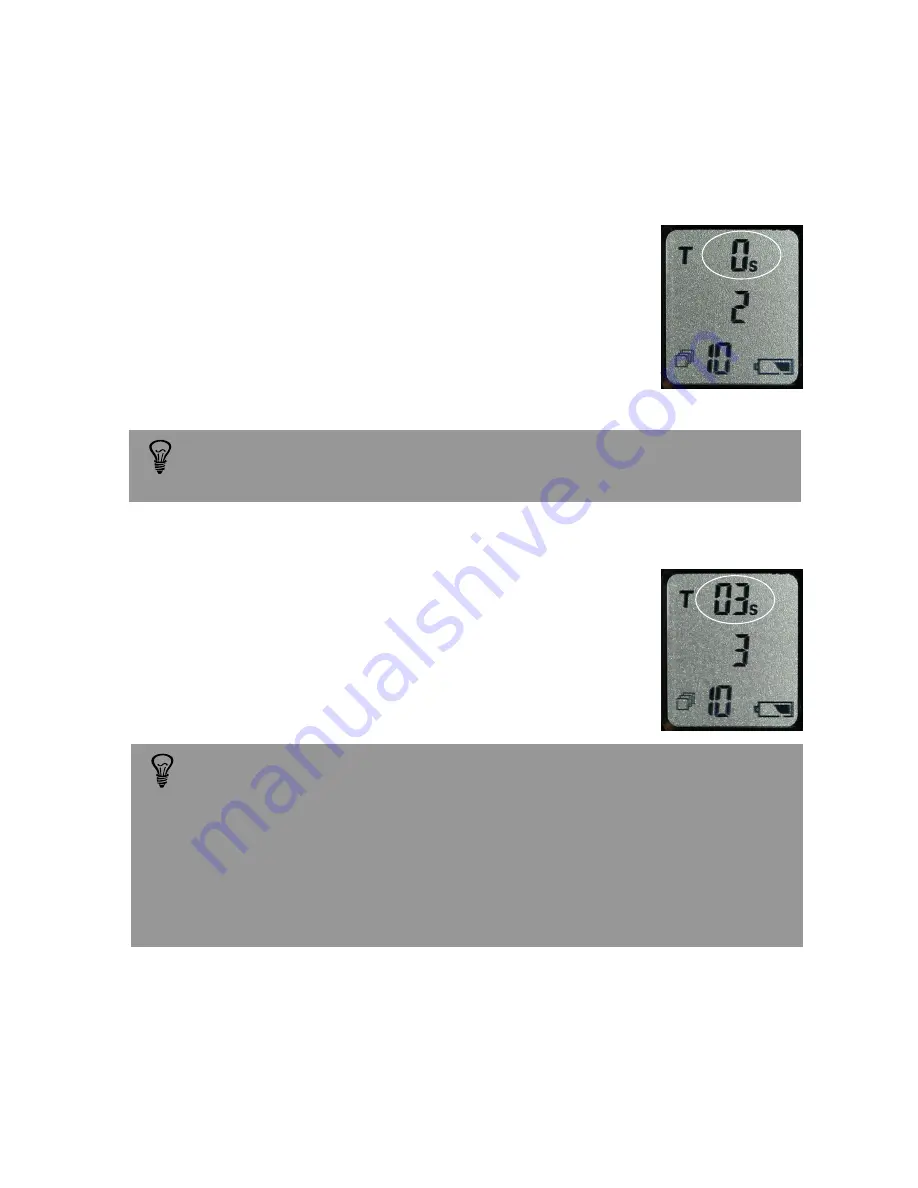
2.4.3 Release signal time (T3)

Press the mode button (6) to activate time function 3. 

„T“

starts to blink on the first line and the number 

„3“

appears on the second line of the display. Set the 

release signal

time with the selection buttons up (7) 

or down (8): 

0.1s, 0.2s, 0.3s, 0.4s, 0.5s, 0.6s, 0.7s, 0.8s or 0.9s

2.4 Speed mode (continued)

To use the VR Drive in the „speed mode“ most effectively, the release signal 
time needs to be set at the lowest possible value. For example, for a Nikon 
D300 or a Canon EOS 50D camera, the minimum release signal time is 0.1s. 
Test your digital camera in „speed mode“ and select the lowest possible 
value. If the release signal time is set too low, then the shutter will be released 
unevenly. If it is set too high, it may not be possible to release all the images 
during the rotation. When the release signal is set at its optimum value, the 
camera will be released with high precision.

2.4.2 Speed mode selection (T2)

Press the mode button (6) a second time. 

„T“

starts to blink on the first line and the number

„2“

appears on the second line of the display. By
choosing selection button down (8) set this time 
to 

0s.

With this setting the VR Drive will release the
camera

non-stop („on the fly“)

.

Select 0s

. If not the VR Drive will be set into the 

“quality mode”

which will 

stop and release the camera in every position.

Summary of Contents for Roundshot VR Drive s

Page 1: ... Manual Roundshot VR Drive version 4 0 January 2010 by Seitz Phototechnik AG Switzerland www roundshot ch page 0 Roundshot VR Drive Roundshot VR Drive s Software release version 4 0 January 2010 Instruction Manual ...

Page 2: ...undshot VR Drive stitched to 1 04 GB panorama 20 900 x 53 743 pixels Photographer Matthias Taugwalder www concept360 ch This product is available in two versions Roundshot VR Drive Roundshot VR Drive s The Roundshot VR Drive is equipped with the quality mode The Roundshot VR Drive s offers both the quality mode and the speed mode It is possible to upgrade a VR Drive to the s version eprom upgrade ...

Page 3: ... T2 16 2 3 3 Time for continuous release T3 17 2 3 4 Degrees of panorama 18 2 3 5 Number of images 18 2 3 6 Ramp 19 2 3 7 Repeat 19 2 3 8 Bracketing 20 2 3 9 Timer 21 2 3 10 Manual release 21 2 3 11 Shut down 21 2 4 Speed mode Roundshot VR Drive s only 22 2 4 1 Rotation time T1 22 2 4 2 Speed mode selection T2 23 2 4 3 Release signal time T3 23 2 4 4 Degrees of panorama 24 2 4 5 Number of images 2...

Page 4: ...a 3 9 VR Drive bracket VR Head 9 VR Drive Panorama Set 1 A B C Adjustment bar for x axis Adjustment bar for y axis Adjustment bar for nodal point Tilt lever to change z axis Y axis X axis Z axis D Electronic release cable Socket for release cable panorama mode Spirit level Display Socket for release cable object movie mode and for charger cable Tripod mount 3 8 2 5 6 7 8 A B C D 1 3 2 Start stop b...

Page 5: ...tart camera 3 Stop camera Ideal for shots in manual mode when the VR Drive should not be touched Practical accessory for precise object photography object movies and for the scanning of cylindrical objects turntable Electronic release cable included in Set Between VR Drive connection 1 and camera plug Starter cable 1 6m other lengths possible Into connection for external release 9 Turntable set Tu...

Page 6: ...ive Panorama Set 2 1 Setting up the VR Drive Panorama Set The VR Head can be separated for easier transport It can be reassembled in the following way Step 2 Place the VR Drive motor on a tripod Step 3 Attach the VR Head on top of the VR Drive motor Make sure that the VR Head is placed firmly on the VR Drive motor Step 1 Assemble the VR Head ...

Page 7: ...ed in an exact 90 angle to the horizon y axis This can be checked with a separate spirit level Step 5 Center the camera in the x and y axis A B Rotate camera with lens pointing downward using the rotation lever D The camera viewfinder now points on the adjustment bar for x axis A Center the camera by shifting its position on the x axis and y axis A B Rotate the camera back in its original position...

Page 8: ...era on the adjustment bar C The basic principle in panoramic photography is to take each shot from the same turning point This central axis is called nodal point If the nodal point is not accurately set the perspectives of the images do not match This mean that points that lie behind each other do not align when viewed from two different turning points Good nodal point Bad nodal point Shifting alo...

Page 9: ...d be either on the very left or very right of the viewfinder screen Then turn the camera and observe the behaviour of vertical lines in the viewfinder If the two lines are still exactly behind each other after turning the camera the nodal point is correctly set If not change the position of the camera on the adjustment bar C forward or backward and repeat this until both lines are perfectly aligne...

Page 10: ...ght and distance values in a 360 rotation vary greatly the automatic light meter and autofocus of the digital camera must be turned off Set the exposure to manual and select an average light reading Focus manually on the lens selecting an intermediate focusing distance The VR Drive and the digital camera are now ready for image taking Setting up the VR Drive Panorama Set is important to obtain the...

Page 11: ...ra is attached vertically to the VR Head which allows a maximum vertical field of view and resolution End product internet multimedia print Media flat panorama or presented in a viewer QTVR flash java shockwave etc 2 2 1 Cylindrical panoramas 180 image taken with Canon 30D 14mm lens and VR Drive Panorama Set in quality mode 360 image taken with Nikon D300 18mm lens and VR Drive Panorama Set in spe...

Page 12: ...th a fisheye lens single row the image quality and resolution are significantly higher Creating a spherical panorama with a fisheye lens and a single row of images is the preferred technique when the camera cannot be tilted for example when the camera is positioned on a mast pole or when the time for image taking or post processing stitching needs to be minimised A spherical panorama 180x360 is cr...

Page 13: ... images 2 2 3 Number of images to create the panorama APS type sensors Full frame sensors The sensor size varies widely from camera to camera Here are some examples width width height height Examples Canon EOS D60 15 1 x 22 7 mm Canon EOS 50D 14 9 x 22 3 mm Canon EOS 450D 14 8 x 22 2 mm Fuji Finepix S5 Pro 15 5 x 23 0 mm Nikon D2x 15 7 x 23 7 mm Nikon D80 15 8 x 23 6 mm Nikon D300 15 8 x 23 6 mm O...

Page 14: ...ed to complete the panorama We recommend a horizontal and vertical overlap of 30 between images This is also the standard overlap required by many stitching programs Here are some sample tables for cameras with APS type sensors full frame sensors and for cameras with digital backs 2 2 3 Number of images to create the panorama continued Cylindrical panoramas 360 30 overlap camera in vertical positi...

Page 15: ...s without tilting 9 images with 45 tilt 1 image with 90 tilt 9 images with 45 tilt 1 image with 90 tilt Single row no tilting Assumptions for above calculations 30 overlap optimised for minimum amount of images and for clic stop positions 15 30 45 60 90 no intermediate tilt angles Multi row with tilt For example with 14mm lens 7 images with 30 tilt 1 image with 90 tilt 7 images with 30 tilt 1 imag...

Page 16: ...mbination and the success of the stitching carefully for spherical panoramas The VR Head tilt lever has convenient click stops up and downward at 15 30 45 60 75 and 90 When tilting at 30 the image taking and stitching workflow is optimised as this requires least images for the stitching Of course it is also possible to tilt at an intermediate angle The exact tilt degrees can be read off the tilt s...

Page 17: ...quality mode the VR Drive stops the camera for every position of image taking allowing maximum quality while allowing the full range of exposure speeds This mode also enables bracketing and manual release of the camera 2 3 1 Rotation time T1 Press the mode button 6 to activate time function 1 T starts to blink on the first line and the number 1 appears on the second line of the display Set the rot...

Page 18: ...ode and bracketing The VR Drive must have a release signal time which is greater than the total time to release the bracketed images in the camera This allows a very fast HDR bracketing Important set the continuous release on your camera and set the required time for continous release in the VR Drive firmware Deactivate the bracketing function in the VR Drive as this is driven by the camera This r...

Page 19: ...on stop without image taking select 0 The degree of rotation from image to image depends on the selected degree of panorama and the number of images For example for a 360 panorama and 12 images the degree of rotation from one image to the next is 30 The number of images depends on the focal length of the lens Wide angle lenses allow to complete the digital panorama in less image steps The number o...

Page 20: ... the image icon starts to blink on the third line of the display Set the smoothness of rotation For a given rotation time the ramp adjusts the speed of acceleration and deceleration with r 1 fastest adjustment r 9 slowest adjustment 2 3 7 Repeat Press the mode button 6 to activate the repeat function The rEP symbol appears on the second line and the image icon starts to blink on the third line of ...

Page 21: ...a s multi shot capability and an extended shutter signal time T3 it is also possible to create an HDR panorama by using the VR Drive bracketing function This technique is used for cameras which do not have a multi shot bracketing feature Activate the bracketing program in the camera and set the number of images and the bracketing in f stops Then enter the number of images per position in the VR Dr...

Page 22: ...st line of the display and the 10 second timer is activated Press the start stop button 5 to start the VR Drive with the 10 second timer 2 3 10 Manual release of the camera Press the mode button 6 to activate the manual mode The new symbol appears on the second line of the display This sets the VR Drive into manual mode Every image needs to be released manually by pressing the start stop button 5 ...

Page 23: ...e otherwise the images will be blurred unsharp 2 4 1 Rotation time T1 Press the mode button 6 to activate time function 1 T starts to blink on the first line and the number 1 appears on the second line of the display Set the rotation time with the selection buttons up 7 or down 8 8s 12s 20s 40s or 60 seconds This time describes a full 360 circle without stops Rotation time T1 s Max shutter speed s...

Page 24: ...D camera the minimum release signal time is 0 1s Test your digital camera in speed mode and select the lowest possible value If the release signal time is set too low then the shutter will be released unevenly If it is set too high it may not be possible to release all the images during the rotation When the release signal is set at its optimum value the camera will be released with high precision...

Page 25: ... for maximum speed for different camera models in the speed mode If the camera does not release evenly increase the rotation time T1 and the release signal time T3 2 4 4 Degrees of panorama Press the mode button 6 to activate the degree function The angle symbol starts to blink on the second line of the display Set the angle with the selection buttons up 7 or down 8 in 45 steps 0 45 90 135 180 225...

Page 26: ...p 2 repeats the sequence from end position With rep 2 or rep 3 the sequence will be repeated non stop Stop the image taking sequence by pressing the start stop button 5 To deactivate the timer press the start stop button 5 or the down power off button 8 for approximately 3 seconds 2 4 7 Timer Press the mode button 6 to activate the timer function The timer symbol starts to blink on the first line ...

Page 27: ... the provided screw Connect the extension cable and the camera release cable in the socket for the release cable 4 This is the lower socket which is also used for recharging the VR Drive Place the digital camera on a tripod and connect the release cable 3 2 Quality mode Please refer to section 2 3 Quality mode of the Roundshot VR Drive Panorama Set The instructions for Panorama Set and Object Movi...

Page 28: ...R Drive in a dry and clean space Start of charging process about 5 minutes Main charging process about 2 hours Charge complete LED 4 1 Recharging the VR Drive The VR Drive is powered by 4 long lasting rechargeable MiMh batteries The battery status is indicated permanently on the display Recharge it with the universal speed charger supplied with the VR Drive Connect the charger to a power source 11...

Page 29: ...cessories are produced from highest quality materials and parts and will provide you continued pleasure Should you nevertheless want to dispose of your Roundshot equipment one day it should not be placed in normal waste The correct disposal of your old equipment is a contribution to preventing possible negative causes for the environment Please contact us to arrange the return shipment and prepare...

Page 30: ...Instruction Manual Roundshot VR Drive version 4 0 January 2010 by Seitz Phototechnik AG Switzerland www roundshot ch page 29 5 Technical Data Technical changes reserved ...

Page 31: ...y 2010 by Seitz Phototechnik AG Switzerland www roundshot ch page 30 Impressum Copyright 2010 by Seitz Phototechnik AG Hauptstr 14 8512 Lustdorf Switzerland ph 41 52 376 33 53 email seitz roundshot ch www roundshot ch Technical changes reserved January 2010 ...

Reviews: