Version Nr. 1-8 - 24.12.2020
Doc. Nr. 99852510S62
20 / 21
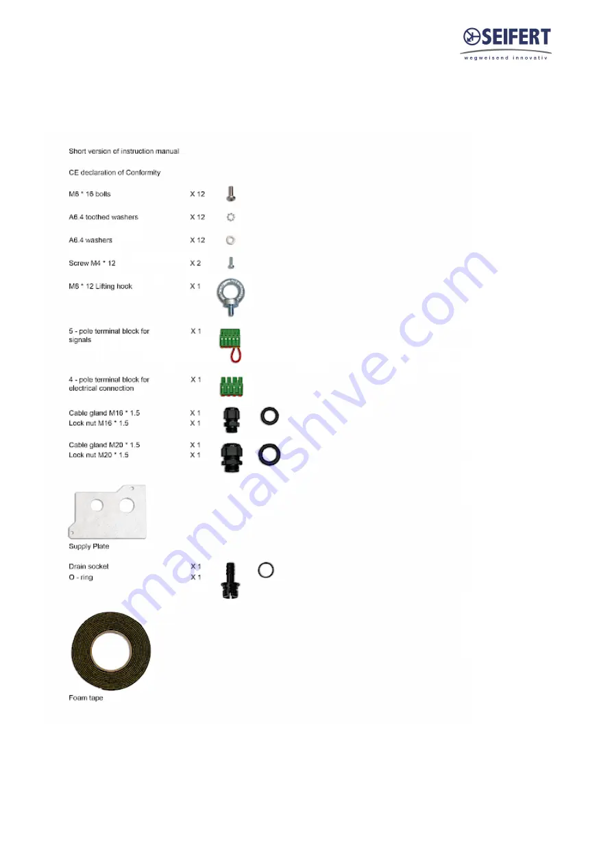
15. Parts supplied / Spare parts / Accessories
Parts supplied:
Page 1: ...2 3 Safety instructions 3 4 Settings 4 5 Functional principle 8 6 Technical data 9 7 Mounting 10 8 Mounting Principle 13 9 Electrical connection 14 10 Wiring diagram 16 11 Taking into operation 17 12 Trouble shooting 18 13 Maintenance Cleaning 18 14 Transport Storage 19 15 Parts supplied Spare parts Accessories 20 ...
Page 2: ... instruction manual must be adhered to General danger Indicates compulsory safety regulations which are not covered by a specific pictogram such as one of the following High electric voltage Indicates electric shock danger Important safety instruction Indicates instructions for safe maintenance and operation of the unit Attention Indicates possible burns from hot components Attention Indicates poss...
Page 3: ...ad with regards to Safety instructions Instructions on taking the cabinet out of operation Instructions on the prevention of unauthorised cabinet reconnection The electric equipment meets the valid safety regulations One can find dangerous voltages above 50 V AC or above 100 V DC Behind the control cabinet doors On the power supply in the unit housing The unit has to be operated according to the ty...
Page 4: ...dditional electrical cabinet heater For the cooling capacities and evironmental ratings please refer to the type plate data Controller The display shows the temperature in the range of 50 C to 150 C 58 F to 302 F The temperature is displayed with resolution of tenths between 19 9 C and 99 9 C 3 8 F to 211 8 F During programming it shows the codes and values of the parameters The display also shows...
Page 5: ...perature units C F low temperature alarm and high temperature alarm 1 Press PRG button for 5 seconds to reach the modifiable parameter list 2 Use or to reach the desired parameter C18 for temperature unit of measure C 0 F 1 P25 for low temperature alarm threshold default 10 C 14 F P26 for high temperature alarm threshold default 55 C 131 F c68 for door contact NO NC logic change 0 ON if closed 1 ON...
Page 6: ...ally closed NC and normally open NO alarm contacts are provided These refer to the alarm state Under normal conditions the NC contact is closed and the NO contact is open When an alarm condition is present or the door contact is open the NC contact will open and the NO contact will close System power failure will give an alarm condition State Alarm relay Display 1 System powered OFF 2 System power...
Page 7: ...compressor s correct operation Contact your service partner E05 Low temperature alarm The measured temperature has fallen below the threshold P25 E07 E08 Controller error Contact your service partner Important Notes Whilst programming if no button is pressed for 10 seconds the display starts flashing and after 1 minute returns to the main display without saving changes To increase scrolling speed p...
Page 8: ... refrigerant thus taking it to high pressure and high temperature and pushes it through the condenser where it is cooled by ambient air thus passing from the gas to the liquid state At the liquid state it then passes through the capillary pipe being a much lower pressure the refrigerant arrives to the evaporator where it absorbs the necessary heat to change from liquid to gas state The gas is then...
Page 9: ...system unimpeded Ambient air circuit 400 706 cfm Cabinet air circuit 295 500 cfm Mounting Wall mounted recessed Housing Material Stainless steel AISI 304 V2A Dimension H x W x D 53 2 x 15 6 x 8 3 inch Weight 103 lbs Voltage Frequency 120 V 60 Hz Current 95F95F 10 8 A Starting current 11 A Max current 19 3 A Nominal power 95F95F 1 23 kW Max power 2 0 kW Fuse 25 A T Connection 5 pole terminal for si...
Page 10: ...t internal and external are not obstructed It must also be ensured in accordance with UL that the air outlet is not blowing air directly at an equipment operator Should this be the case a barrier or duct shall be provided to redirect the airflow Cooling unit enclosure air suction hole must be installed in the highest possible point When installing the unit on a door ensure it can take the weight Be...
Page 11: ... Nr 1 8 24 12 2020 Doc Nr 99852510S62 11 21 Cold air outlet duct When using a cold air outlet duct please follow the steps below Filter installation If you install replace a filter please follow the steps below ...
Page 12: ...ted condensate evaporation of the cooling unit releases the condensate to the environment If condensate formation is too great additional condensate can drip into an overflow trough which then drains off on the ambientt side In order to prevent the formation of excessive condensate you should nevertheless check the seals at regular intervals consider installing a door contact switch order no 3100001...
Page 13: ... after installation Use only the supplied mounting hardware Tighten Screws to 4 5 Nm Ensure the mounting surface does not warp after assembly and reinforce it if necessary 1 M6 screws 2 M6 toothed washers 3 M6 flat washers 4 Enclosure 5 Mounting gasket 6 Lifting hook 7 Cover 8 M4 screws Fig 1 Recessed Fig 2 External ...
Page 14: ...is can be set by changing the value of parameter c68 Refer to the table below and section Controller Setting temperature units C F low temperature alarm door contact logic section for more information c68 0 default ON if closed Door contact terminals bridged or NC door switch connected contact must be closed when cabinet door is closed c68 1 ON if open Remove bridge or NO door switch connected con...
Page 15: ...12 2020 Doc Nr 99852510S62 15 21 Connect unit Connect the cooling device according to the instructions below The cable cross section must correspond to the required power for the current consumption but max 2 5 mm AWG 14 ...
Page 16: ...Version Nr 1 8 24 12 2020 Doc Nr 99852510S62 16 21 10 Wiring diagram Power connector 1 L1 2 3 N 4 PE Signal connector 1 Alarm NC 2 Alarm COM 3 Alarm NO 4 Door contact 5 Door contact ...
Page 17: ... be protected with a MCB Type D or K Upon connection the internal fan will start working If the temperature inside the enclosure is higher than the set value of the controller both the compressor and external air fan start working The cooling cycle will either stop once the air inside the enclosure reaches the set temperature minus hysteresis or once the minimum On time is reached The hysteresis i...
Page 18: ...t leakage Contact dealer service center Excessive condensate Enclosure door open Ambient air gets into the enclosure Ensure door is closed add a door switch and connect it to controller Enclosure door closed Enclosure IP protection class is below IP54 Seal all openings of the enclosure Damaged or misplaced sealing strip Repair sealing strip accordingly 13 Maintenance Cleaning Always switch power s...
Page 19: ...s temperature range 40 F to 158 F Relative humidity at 77 F max 95 The cooling unit should always be stored according to the installation position Returning the unit To avoid transport damage the unit should be returned in the original packing or in a packing case and must be strapped to a pallet If the unit cannot be returned in the original packing please ensure that A space of at least 30 mm mu...
Page 20: ...Version Nr 1 8 24 12 2020 Doc Nr 99852510S62 20 21 15 Parts supplied Spare parts Accessories Parts supplied ...
Page 21: ...ashable aluminium filter AC 8515 20 25 BF 1 Cold air outlet duct AC 8515 20 25 BZ 1 Anti vibration kit AC 8515 20 25 BY 1 Door switch contact 3100001 Seifert Systems GmbH Seifert Systems Ltd Seifert Systems AG Seifert Systems Inc Seifert Systems Pty Ltd Albert Einstein Str 3 HF09 10 Wilerstrasse 16 75 Circuit Drive 105 Lewis Road Hal Far Industrial Estate North Kingstown Wantirna South 42477 Radevo...