background image

Version No. 1-7 - 08.08.2022

Doc. No. 9943051001

15 / 19

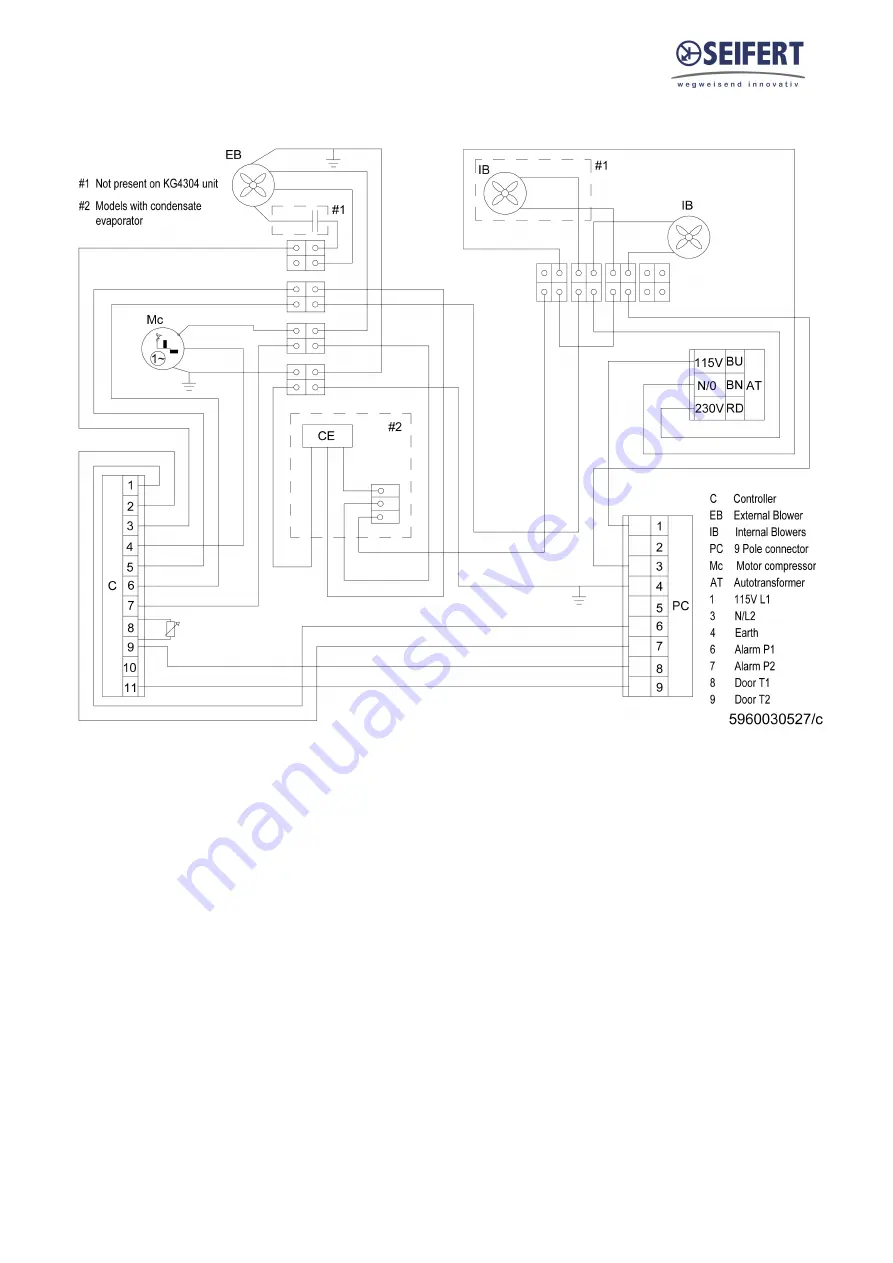
14. Wiring Diagram

Summary of Contents for 43051001

Page 1: ...onal principle 6 6 Technical data 7 7 Performance graph 8 8 Mounting 9 9 Mounting Principle 10 10 Cut Out Dimension 11 11 Dimension H x W x D 12 12 Electrical Connection 13 13 Controller 14 14 Wiring...

Page 2: ...issipation of heat from control cabinets and enclosures stationary not moving in order to protect temperature sensitive components in an industrial environment To meet the conditions of use all the in...

Page 3: ...nits based on the information diagrams or descriptions contained in this manual No liability can be accepted for damage and production caused by Disregarding the instruction manual Operating error Ina...

Page 4: ...regulations One can nd dangerous voltages above 50 V AC or above 100 V DC Behind the control cabinet doors On the power supply in the unit housing The unit has to be operated according to the type pl...

Page 5: ...air does not come into contact with the ambient air which may well be dirty or polluted Enclosure cooling units can dissipate large quantities of heat from sealed enclosures such as electrical enclos...

Page 6: ...e capillary pipe being a much lower pressure the refrigerant arrived to the evaporator where it absorbs the necessary heat to change from liquid to gas state The gas is then drawn back into the compre...

Page 7: ...stem unimpeded Ambient air circuit 435 550 m h Cabinet air circuit 200 250 m h Mounting Wall mounted Housing Material Mild steel powder coated Dimensions A x B x C D E 651 4 x 315 x 260 mm Weight 33 7...

Page 8: ...Version No 1 7 08 08 2022 Doc No 9943051001 8 19 7 Performance graph...

Page 9: ...e case a barrier or duct shall be provided to redirect the air ow Cooling unit enclosure air suction hole must be installed in the highest possible point When installing the unit on a door ensure it c...

Page 10: ...No 9943051001 10 19 9 Mounting Principle Do not use within the rst 15 minutes after installation 1 M6 screws 2 M6 at washers 3 M6 toothed washers 4 Cabinet 5 Sealing tape 6 Cooling unit 7 Lifting hook...

Page 11: ...Version No 1 7 08 08 2022 Doc No 9943051001 11 19 10 Cut Out Dimension...

Page 12: ...Version No 1 7 08 08 2022 Doc No 9943051001 12 19 11 Dimension H x W x D...

Page 13: ...are disconnected from the electrical supply and protected against unauthorised accidental reconnection Ensure that the unit and the enclosure are switched o before opening the unit While servicing and...

Page 14: ...ress Set to save the new setting To change the heating set point St2 units with internal heater only 1 Press Set till St1 appears on the display and release the button 2 Press again Set till St2 appea...

Page 15: ...Version No 1 7 08 08 2022 Doc No 9943051001 15 19 14 Wiring Diagram...

Page 16: ...power supply connector is incorrect Change phases inside power supply connector Unit doesn t cool External and internal fan work compressor does not work Compressor motor electrical failure Have comp...

Page 17: ...ions which meet the following conditions temperature range 40 C to 70 C Relative humidity at 25 C max 95 Returning the unit To avoid transport damage the unit should be returned in the original packin...

Page 18: ...1 Mounting template 1 M6 16 bolts 8 A6 4 washer 8 M6 toothed washers 8 Lifting hook M8 x 12 1 PVC washer 1 Drain pipe 1 Female connector 1 Foam tape Accessories Description Order no Fibre lter media...

Page 19: ...tate North Kingstown Wantirna South 42477 Radevormwald Birzebbuga BBG 3000 4563 Gerla ngen 4901 Ottnang 26100 Cremona RI 02852 3152 Victoria Germany Malta Switzerland Austria Italy USA Australia Tel 4...

Reviews: