background image

Smart Positioner

SP740 Series

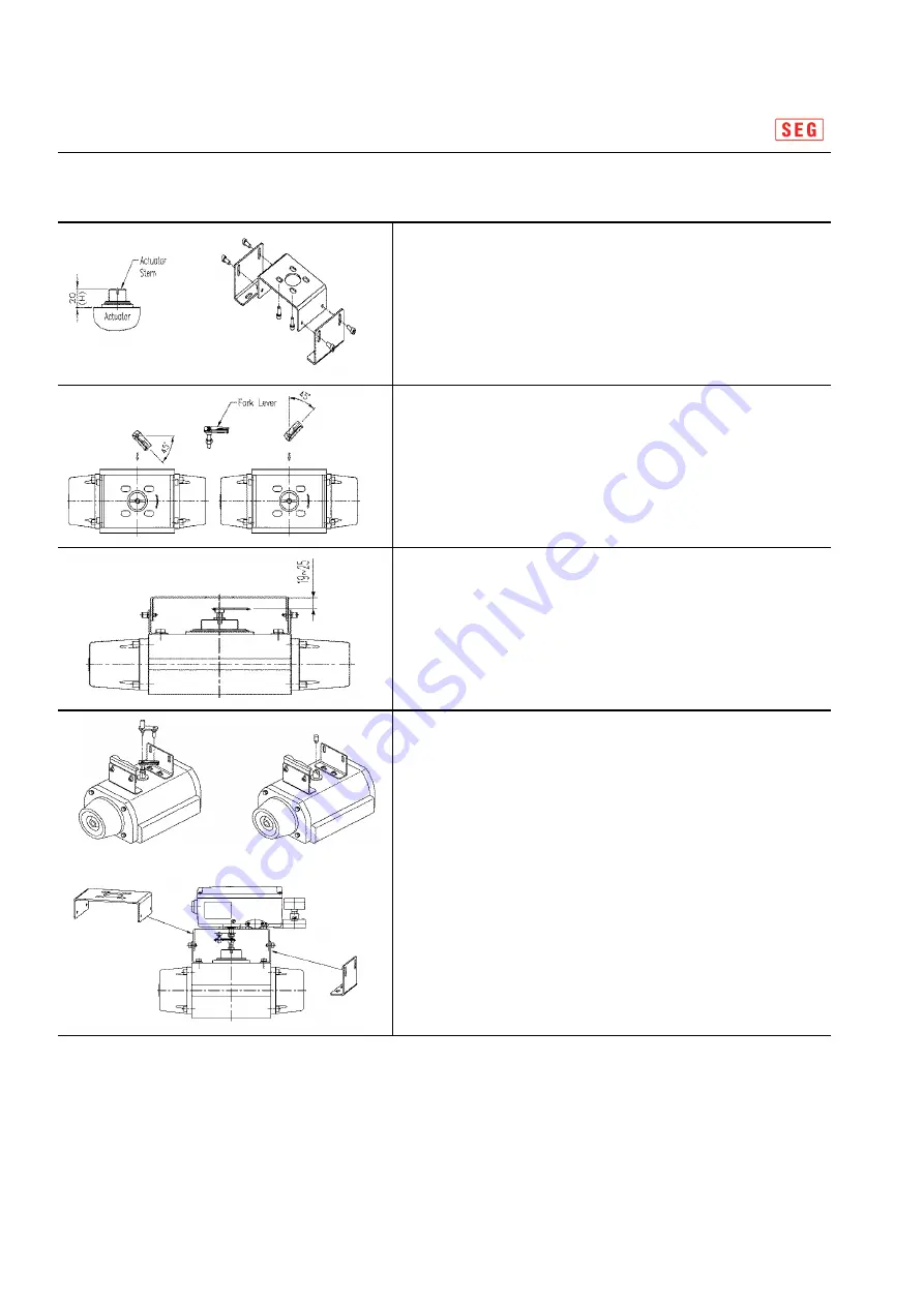
3.4.2 Rotary Positioner Installation Step

 Connect upper/lower bracket assemblies onto an actutor

    with bolts.  Note the positioner manufacturer does not supply 

    bolts to fix an actuator.

 With an actuator's initial start point of 0%, install the

     fork lever as seen in figure according to the rotation 

     direction of stem.  

     Make sure the installation degrees of fork lever

     Should be 45 degrees from the horizontal axis.

 If  fork lever position is setting , tighten the nuts,

    which is assembled with the lower part of fork lever, 

    to an actuator stem firmly. At the moment, fork lever 

    upper side and the upper bracket's distance  should be 

    19 to 25 mm each other.

Actuator

Lower/upper bracket

Clockwise / counterclockwise

Fork lever assembling height 

setting

22/40

 Attach the positioner onto upper bracket and fix it with bolts.

    At the moment, insert the pin on the lower part of

    the fork lever into the hole of fork lever so to be centered. 

    When tightening bolts, do not tighten ane bolt firmly 

    and after loosing 4 pcs of bolt slightly and 

    after checking positioner's connection, connect bracket

    completely. 


Namur type installation is very simple because there is

   sufficient length and  end of shaft  is machined

   so that it may be insert into actuator stem pin directly. 

FORK LEVER TYPE

NAMUR TYPE

22/40

Summary of Contents for SP740 Series

Page 1: ...INSTRUCTION MANUAL SMART POSITIONER SP740 Series 1 40 SP 4MIS V1 1 SA 6 10 2019 Shin Hwa Eng Co Ltd Software ver Manual ver 1 40...

Page 2: ...12 2 10 13 2 10 1 SP740 Standard Type 13 2 10 2 SP740 Lever Type 14 2 10 3 SP740 Fork Lever Type 15 2 10 4 SP740 Namur Type 16 Products Dimension Products code 2 40 2 10 4 SP740 Namur Type 16 3 Insta...

Page 3: ...8 6 1 30 8 6 2 31 8 6 3 31 8 7 31 8 7 1 SV NORM 32 Run Mode RUN Hand Calibaration Mode HAND CAL Manual Mode MANUAL Parameter Mode PARAMETER Dead Zone DEADZONE KP_UP KP_UP KP DOWN KP_DOWN Auto PV Calib...

Page 4: ...our safety and properties To classify the level of severity or urgency of risk it is divided into 3 levels like Caution Warning Danger 4 40 Do not try to handle or disassemble the machine until the sa...

Page 5: ...ty current only please connect instrinsic safety protection devices To prevent the the risk of explosion it is necessary to install the product according to the basic safety instruction to operate in...

Page 6: ...ugh a barrier limiting the electrical specification higher than described in the above 2 8 Besides installation and wiring etcs relative contents should be observed and worked and used 2 2 Features It...

Page 7: ...cate model number according to model specification Instrinsic safety Non explosion grade Indicate Instrinstic Safety proof 7 40 Indicates necessary electric data which is composed into instrinsic saft...

Page 8: ...Safe Fail Lock 1 Non explosion IP66 2 Intrinsic safety Ex ia C T5 T6 G Air PT1 4 Conduit G PF 1 2 N Air NPT1 4 Conduit NPT1 2 Explosion proof Connection Position L S Lock condition Acting type Lever T...

Page 9: ...on Input Signal 4 20mA DC Minimum Current Signal 2 8mA Standard 3 8mA HART Included Impedance Max 450 20mA DC Motion type Linear Rotary Linear Rotary Model SP740S SP740D Acting Type Single Double 9 40...

Page 10: ...changed input current is delivered to coil 6 of Torque motor 1 so to be properly located while repeating till it is balanced On the contraray if input current is lower Nozzle Flapper 9 blocks Nozzle 8...

Page 11: ...certificate Limit switch 28V 93mA 651mW 0nF 0uH Dry contact type Feedback signal power 28V 93mA 651mW 3nF 35uH Main power 28V 93mA 651mW 3nF 35uH Barrier specifications Ui Ii Pi Ci Li IEC 60079 11 201...

Page 12: ...ositioner SP740 Series 2 9 Structure 12 40 Fig 2 4 Schematic View SP740 Series Schematic View COVER Potention meter PCB Cover Pilot Control PCB Pilot Valve Torque Motor Base Body Main Shaft Cage Block...

Page 13: ...Smart Positioner SP740 Series 2 10 Products Dimension 2 10 1 SP740 Standard Type 13 40 Fig 2 5 SP740 Standard Type 13 40...

Page 14: ...Smart Positioner SP740 Series 2 10 2 SP740 Lever Type 14 40 Fig 2 6 SP740 Lever Type 14 40...

Page 15: ...Smart Positioner SP740 Series 2 10 3 SP740 Fork Lever Type 15 40 Fig 2 7 SP740 Fork Lever Type 15 40...

Page 16: ...Smart Positioner SP740 Series 2 10 4 SP740 Namur Type 16 40 Fig 2 8 SP740 Namur Type 16 40...

Page 17: ...rs Monkey or Spanner 3 3 Linear positioner Installation 3 3 1 Caution on Installation When fabricating bracket and connecting lever to actuator the followings 2 kind of contents Warning 17 40 When fab...

Page 18: ...osed bracket and bolts Figure 3 2 18 40 Assemble with the enclosed bracket and bolts Connect positioner brackeck with boits in actuator yoke Tighten bolts loosely so that they may be modified location...

Page 19: ...feed back lever hole as seen as figure Figure 3 3 19 40 hole as seen as figure Insert connection bar between lever and lever spring correctly Check whether positioner feed back lever is leveled horizo...

Page 20: ...be consisted with feed back lever s value and full stroke value s equal point If positioner lever and actuator connection bar has not consistent move and adjust positioner bracket or connection bar S...

Page 21: ...0 Namur type 3 4 1 Bracket Set assembly for Rotary Positioner Installation Lower bracket 2 pcs Fig3 6 Fig 3 7 NAMUR TYPE 21 40 Lower bracket 2 pcs Upper bracket 1 pcs Bolts for upper lower brackets M6...

Page 22: ...uator stem firmly At the moment fork lever upper side and the upper bracket s distance should be 19 to 25 mm each other Actuator Lower upper bracket Clockwise counterclockwise Fork lever assembling he...

Page 23: ...actuator A single positioner should use OUT1 port only Therefore in case of using a single acting spring return actuator make sure to connect a positioner s OUT1 port and actuator s supply pressure po...

Page 24: ...lower than described currenct and votlage Do not install cable on near equipments incurred by noise such as high capacity transformer or motor 5 2 Terminal Connection Warning 1 input signal 2 input s...

Page 25: ...stallation place and maintain the ground resistance as equal as the product and barrier Fig 5 3 Instrinsic safety parts terminal connection 5 5 Ground Standard P C B Board or Standard P C B Board Hart...

Page 26: ...mit Switch Adjustment To adjust the operation location of a limit switch looseen the CAM fixed screw rotate it to a desirable position and tighten screw again 26 40 Fig 6 1 Adjusting the operation loc...

Page 27: ...mounted as added function There are four type PCB as followings Fig 7 1 Standard PCB board Fig 7 2 Standard PCB board limit switch type 27 40 Types of PCB Option Hart Hart Hart Hart HART board HART bo...

Page 28: ...or designated parameter value ESC It is used when returning from the current menu to a higher one step menu 8 3 Run Mode RUN After connecting power to the positioner RUN PV mode shall be appeared on...

Page 29: ...alibaration AUTO PV AUTO PV re set Zero Point 0 and End Point 100 only Execute AUTO CAL without changing existing parmeter value It is used when the positioner s installation position is slightly chan...

Page 30: ...hows 30 0 8 6 Parameter Mode PARAMETER If executing AUTO ALL actuator control condition can be set by optimal operation condition only AUTO calibration may be difficulty to optimize setting In this ca...

Page 31: ...st operation velocity until instruction position It is used when driving facilities are so small or when friction load is too high the downward velocity is too slow ENTER 5 secs UP 2 times ENTER ENTER...

Page 32: ...value or reverse value i e In NORM current position 0 can be converted into 100 in REV ENTER UP DOWN ESC 3 times UP DOWN ESC 3 times ENTER UP 2 times ENTER ENTER 5 secs UP 3times ENTER ENTER UP 1 time...

Page 33: ...when using this function This works should be when executing air block or in 50 position Actuator shall be operated into reverse direction 8 8 2 Valve Flow Characteriization Curve mode CHAR LN UP DOW...

Page 34: ...totally and partially If some of parts should be changed and others are remain it can be escaped in ESC during setting after 1 sec ESC UP UP P 10 times ENTER UP 2 ENTER UP DOWN 34 40 SET POINT 0 and 1...

Page 35: ...osition as Tight Shut Close value set as 0 basically When user want to change opening value if rhe instruction value is input below setting value the driving position return into 0 immediately i e if...

Page 36: ...Oy od Indicates consumption year s and consumption day s Indicates error and warning code occurred Please refer to 14 1 or 14 2 Current temperature ERROR TEMP 4 18 0Y Od It is total consumption time o...

Page 37: ...e Error contents and cause Action air pressure is normal or not be supplied normally and take action that they may Check that positioner s supplying 37 40 An error code is immediately displayed on LCD...

Page 38: ...e and the state lasts a minute ERROR_06 Indicates that SV and PV s tolerance is over 5 and it continues Indicates that valve friction is too large or input pressure is too low Check in the error of Vi...

Page 39: ...Smart valve positioner SP740 Series 10 LCD Operation Map 39 40 39 40...

Page 40: ...G Co Ltd Address 242 Cheongneungdae ro Gojan dong 80B 2L Namdong gu Incheon Korea ZIP code 21695 Rep TEL 032 817 8030 Rep Fax 032 815 8036 Rep Email 8030 seg co kr Website http www seg co kr COPYRIGHT...

Reviews:

Related manuals for SP740 Series