background image


# Raspberry Pi + Grove  Grove Relay 


import time 

import grovepi 

# Connect the Grove Switch to digital port D3 

# SIG,NC,VCC,GND 


switch = 3 

# Connect the Grove Relay to digital port D4 

# SIG,NC,VCC,GND 


relay = 4 

grovepi.pinMode(switch,"INPUT") 

grovepi.pinMode(relay,"OUTPUT") 

while True: 

    try: 

        if grovepi.digitalRead(switch): 

            grovepi.digitalWrite(relay,1) 

        else: 

            grovepi.digitalWrite(relay,0) 

            time.sleep(.05) 

    except KeyboardInterrupt: 

        grovepi.digitalWrite(relay,0) 

        break 

    except IOError: 

        print "Error" 

Run the program 


Find the path to the file(According to your own path)


   cd GrovePi/Software/Python/ 


Run Program 

   sudo python grove_switch_relay.py 

Summary of Contents for Grove-Relay

Page 1: ...1 Grove Relay User Manual Version 1 0 Release date 2015 9 22 Wiki http www seeedstudio com wiki Grove_ _Relay Bazaar http www seeedstudio com depot Grove Relay p 769 html cPath 39_42 ...

Page 2: ...2 Document Revision History Revision Date Author Description 1 0 Sep 22 2015 Loovee Create file ...

Page 3: ...3 Contents Document Revision History 2 1 Introduction 2 2 Specifications 3 3 Usage 4 3 1 With TI LaunchPad 4 3 2 With Arduino 5 3 3 With Raspberry Pi 5 4 Resources 7 ...

Page 4: ...ision of Seeed Technology Inc this manual has been compiled and published which covered the latest product description and specification The content of this manual is subject to change without notice Copyright The design of this product including software and its accessories is under tutelage of laws Any action to violate relevant right of our product will be penalized through law Please conscious...

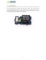
Page 5: ... module is a digital normally open switch Through it you can control circuit of high voltage with low voltage say 5V on the controller There is an indicator LED on the board which will light up when the controlled terminals get closed ...

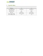
Page 6: ...v1 1 v1 2 Product Release Date 27th Jan 2013 9th June 2014 Operating Voltage 5V 3 3 5V Operating Current 60mA 100mA Relay Life 100 000 Cycle 100 000 Cycle Max Switching Voltage 250VAC 30VDC 250VAC 30VDC Max Switching Current 5A 5A ...

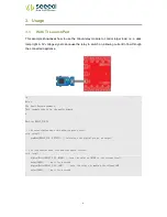
Page 7: ...Energia example This example code is in the public domain define RELAY_PIN 39 the setup routine runs once when you press reset void setup pinMode RELAY_PIN OUTPUT initialize the digital pin as an output the loop routine runs over and over again forever void loop digitalWrite RELAY_PIN HIGH turn the relay on HIGH is the voltage level delay 1000 wait for a second digitalWrite RELAY_PIN LOW turn the ...

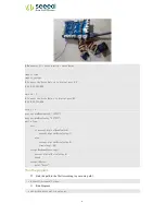
Page 8: ...lose Project Five Relay Control void setup pinMode 1 INPUT pinMode 2 INPUT pinMode 6 OUTPUT void loop if digitalRead 1 HIGH digitalWrite 6 HIGH delay 100 if digitalRead 2 HIGH digitalWrite 6 LOW 3 3 With Raspberry Pi This sample is show you how to use Grove Relay by Raspberry Pi The demo below will show that the relay be control by Grove Button ...

Page 9: ...vepi pinMode switch INPUT grovepi pinMode relay OUTPUT while True try if grovepi digitalRead switch grovepi digitalWrite relay 1 else grovepi digitalWrite relay 0 time sleep 05 except KeyboardInterrupt grovepi digitalWrite relay 0 break except IOError print Error Run the program Find the path to the file According to your own path cd GrovePi Software Python Run Program sudo python grove_switch_rel...

Page 10: ...7 4 Resources Grove Relay Eagle File Relay_Datasheet how to upload code Buy it ...

Page 11: ...Mouser Electronics Authorized Distributor Click to View Pricing Inventory Delivery Lifecycle Information Seeed Studio 103020007 ...

Reviews: