Secutron Inc.
41
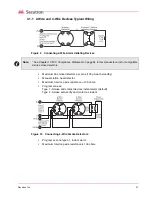
6.1.1 Using the LED Indicators to Program the System
The Panel Status LED Indicators display the current Programmable function.
The Zone Indicator LEDs display the options for the current Programmable function.
For a further explanation of the LED Indicators see Figure 18 Using the LED Indicators to
Program the System.
Figure 18 Using the LED Indicators to Program the System
6.1.2 Using the Silence Trouble and Silence Alarm Controls to Program the
System
Pressing the Signal Silence button cycles you to the next setting for the current programmable
function.
Pressing the Silence Trouble button cycles to the next programmable function.
6.1.3 Using the Reset System and Lamp Test Controls
Pressing the Reset System control enters the Reset Programming Mode. For more
information see 6.3.7 Entering the Reset Programming Mode on page 48.
Pressing the Lamp Test control enters the View Event Buffer mode. For more information see
6.4 Viewing the Event Buffer on page 51.
Figure 19 Using the Controls to Program the System
CPU
FAULT
Zone LEDs display the current Zones or
Option being configured
Panel Status LEDs display which current
Programmable function being configured
ALARM, SUPV, CPU FAULT and AC are NOT USED
in Programming Mode
Trouble LED flashes when panel
is in Programming Mode
Summary of Contents for MR-2605
Page 2: ......
Page 6: ...Secutron Inc vi...
Page 8: ...Secutron Inc viii...
Page 10: ...Secutron Inc x...
Page 70: ...Secutron Inc 70...
Page 71: ......


