


v2.0 1/12/11
4
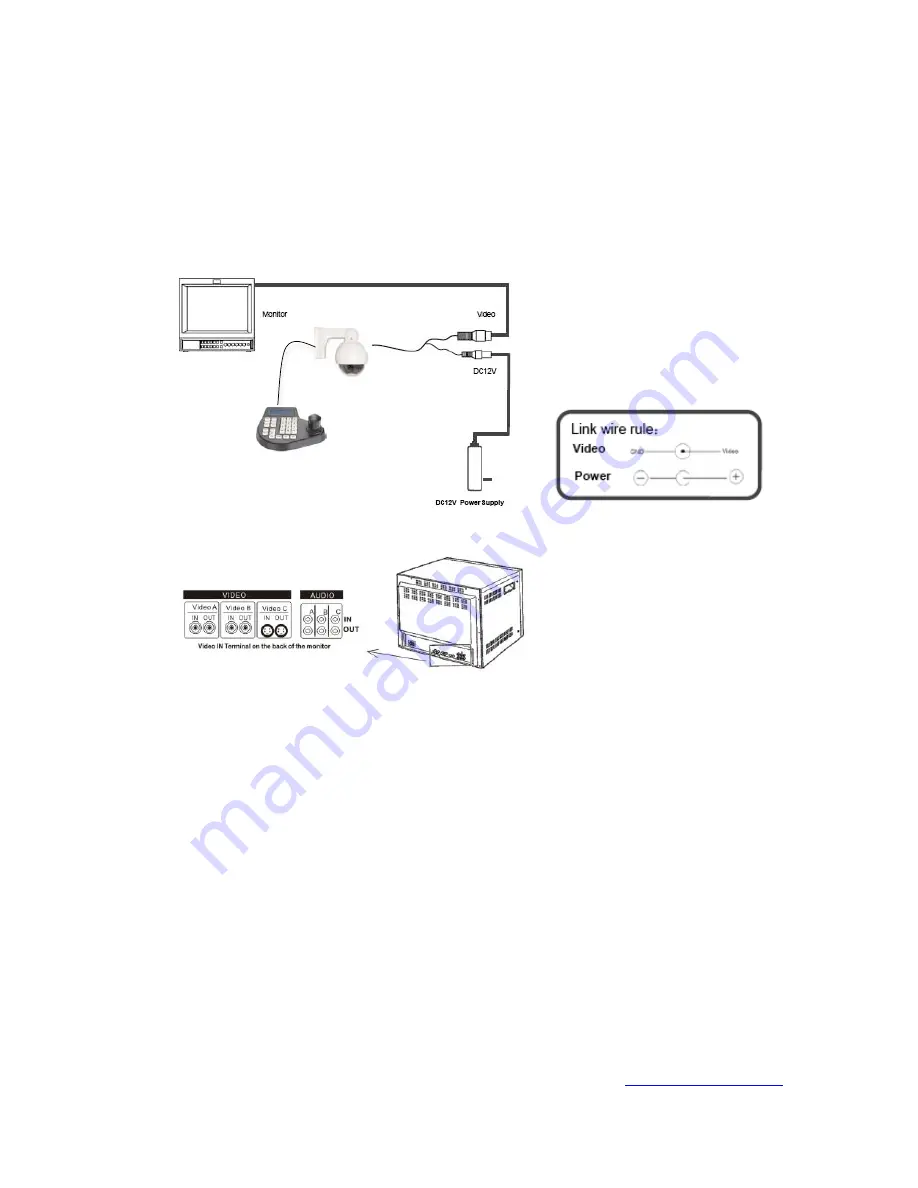
4. WIRING CONNECTIONS
a. Connect the power supply’s DC plug to the camera’s power outlet.
b. Connect the camera to the monitor with a 75
Ω
coaxial video cable.
c. Connect power supply’s AC plug to a suitable AC power outlet.
d. Connect the RS485 terminals to a suitable PTZ controller that supports the PELCO-D
protocol. Violet is RS485 + and Gray is RS485 -.
5. TROUBLESHOOTING
a. No picture after applying power – (i) check all plugs and cables are securely
connected to the proper connectors; (ii) ensure your power supply is providing the
correct voltage and current.
b. The picture has ripples – (i) check to see if the power supply is experiencing AC ripple,
if so a filter may be required; (ii) determine if the monitor is faulty; (iii) determine if
other peripheral equipment is causing ripple and if so make the necessary
adjustments.
c. The picture background continuously changes color – a fluorescent lamp’s magnetic
field may cause color roll, therefore, reduce the number of fluorescent lamps or
increase the distance between the camera and the lamps.
d. The picture appears smeared – (i) the power supply voltage level may be unstable,
therefore, try another power supply; (ii) ensure the cables are correctly connected
and/or the cables are of the correct impedance.
e. Other interference may require a SecurityTronix ground loop isolation filter.
f. If the camera will not respond to the PTZ controller ensure the controller baud and
protocol settings are consistent with the camera (e.g., 2400 baud, PELCO-D). Also
ensure the camera’s address matches the controller. Finally, check that the camera’s
control cable polarity is connected properly to the controller.
g. Additional troubleshooting assistance can be found on-line at
www.securitytronix.com
in addition to support from SecurityTronix sales engineers at 1-610-429-1511.


