Security Camera King TVIOD-PR2EXIR User Manuals Download Page 4

1


Introduction 

1.1


Product Features 

The camera is applicable for both indoor and outdoor 
conditions, and the application scenarios include road, 

warehouse, underground parking lot, bar, etc.. 

The main features are as follows: 

High performance CMOS sensor 

Low illumination, 0.005 Lux @ (F2.0, AGC ON), 0 Lux 

with IR 

IR cut filter with auto switch

OSD menu with configurable parameters

Auto white balance 

Internal synchronization

SMART IR mode 

PoC (with -E) 

3-axis adjustment

1.2


Overview 

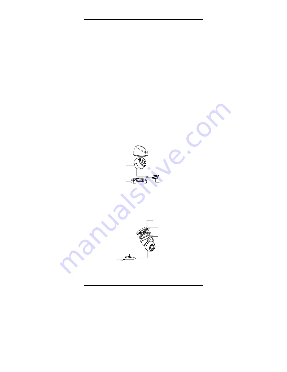
This manual applies to two types of turret cameras. 
The overviews of each type are shown in the figures 

below. 

1.2.1


Overview of Type I Camera 

Main Body

Mounting Base

Enclosure

Video Cable

 Power Cord  
12 VDC

Figure 1-1


Overview of Type I Camera 

1.2.2


Overview of Type II Camera 

Enclosure

Mounting Base

Video Cable

Power Cord 

12 VDC  

Camera

Trim Ring

Clip Plate

Figure 1-2


Overview of Type II Camera 

2


Installation 

Before you start: 

Make sure that the device in the package is in good 
condition and all the assembly parts are included.

Make sure that all the related equipment is power-off
during the installation.

Check the specification of the products for the
installation environment.

Check whether the power supply is matched with 
your required output to avoid damage.

Make sure the wall is strong enough to withstand 
three times the weight of the camera and the 
mounting.

Summary of Contents for TVIOD-PR2EXIR

Page 1: ... contact the dealer This manual may contain several technical incorrect places or printing errors and the content is subject to change without notice The updates will be added to the new version of this manual We will readily improve or update the products or procedures described in the manual TVIOD PR2EXIR ...

Page 2: ...This device must accept any interference received including interference that may cause undesired operation EU Conformity Statement This product and if applicable the supplied accessories too are marked with CE and comply therefore with the applicable harmonized European standards listed under the Low Voltage Directive 2014 35 EU the EMC Directive 2014 30 EU 2012 19 EU WEEE directive Products mark...

Page 3: ... mounting is adopted If smoke odor or noise rise from the device turn off the power at once and unplug the power cord and then contact the service center Never attempt to disassemble the camera by unprofessional personal Cautions Do not drop the camera or subject it to physical shock Do not touch senor modules with fingers If cleaning is necessary use clean cloth with a bit of ethanol and wipe it ...

Page 4: ...ures below 1 2 1 Overview of Type I Camera Main Body Mounting Base Enclosure Video Cable Power Cord 12 VDC Figure 1 1 Overview of Type I Camera 1 2 2 Overview of Type II Camera Enclosure Mounting Base Video Cable Power Cord 12 VDC Camera Trim Ring Clip Plate Figure 1 2 Overview of Type II Camera 2 Installation Before you start Make sure that the device in the package is in good condition and all t...

Page 5: ...coin 3 Paste the drill template supplied to the place where you want to install the camera 4 Drill the screw holes and the cable hole optional on the ceiling wall according to the drill template Screw Hole Cable Hole Figure 2 2 Drill Template Note Drill the cable hole when adopting the ceiling outlet to route the cable 5 Attach the mounting base to the ceiling wall and secure them with supplied sc...

Page 6: ... and down to adjust the tilt position 0 to 75 3 Rotate the camera body to adjust the rotation position 0 to 360 2 1 2 Mounting with Inclined Base Steps 1 Paste the drill template supplied to the place where you want to install the camera 2 Drill screw holes and the cable hole on the ceiling wall according to the supplied drill template Screw Hole Cable Hole Figure 2 6 The Drill Template 3 Disassem...

Page 7: ...iling mounting will be taken as an example in this section You can take steps of ceiling mounting as the reference when adopting the wall mounting Steps 1 Disassemble the turret camera by rotating the camera to align the notch to the clip plate as shown in the Figure 2 10 Notch Clip Plate Figure 2 10 Disassemble the Camera 2 Pry the mounting base to remove the mounting base from the camera body 3 ...

Page 8: ...he corresponding cables such as power cord and video cable 9 Power on the camera to check whether the image on the monitor is gotten from the optimum angle If not adjust the camera according to the figure below to get an optimum angle Tilt Position 0 to75 Pan Position 0 to 360 Rotation Position 0 to 360 Figure 2 14 3 axis Adjustment 1 Hold the camera body and rotate the enclosure to adjust the pan...

Page 9: ...y Junction Box Body Junction Box Cover Figure 2 16 Fix the Junction Box 7 Repeat steps 6 to 9 of 2 1 1 Ceiling Wall Mounting without Junction Box to install the camera to the junction box 2 3 2 Wall Mounting Before you start You need to purchase a wall mounting bracket separately Steps 1 Drill four screw holes in the wall according to the holes of the bracket 2 Install the bracket to the wall by a...

Page 10: ...era with the TVI DVR and the monitor shown as the figure 3 1 Camera TVI DVR Monitor Figure 3 1 Connection 2 Power on the analog camera TVI DVR and the monitor to view the image on the monitor 3 Click PTZ Control to enter the PTZ Control interface 4 Call the camera menu by clicking button or call preset No 95 AE WB BRIGHTNESS MAIN MENU FORMAT LANGUAGE DAY NIGHT VIDEO SETTINGS FUNC RESET SAVE EXIT P...

Page 11: ...brightness of the image You can set the brightness value from 1 to 10 to darken or brighten the image The higher the value the brighter the image is EXPOSURE MODE You can set the EXPOSURE MODE as GLOBAL BLC and WDR GLOBAL GLOBAL refers to the normal exposure mode which adjusts lighting distribution variations and non standard processing BLC Backlight Compensation BLC Backlight Compensation compens...

Page 12: ...e of the scene illumination MWB Manual White Balance You can set the R GAIN B GAIN value from 1 to 255 to adjust the shades of red blue color of the image WB MODE R GAIN B GAIN RETURN MWB 5 5 Figure 3 4 MWB MODE 3 3 3 DAY NIGHT Color BW Black White and AUTO are selectable for DAY and NIGHT switches COLOR The image is colored in day mode all the time B W The image is black and white all the time an...

Page 13: ...ages in low light conditions and delivering more accurate and sharp image quality You can set the DNR value from 1 to 10 MIRROR DEFAULT H V and HV are selectable for mirror DEFAULT The mirror function is disabled H The image flips 180 horizontally V The image flips 180 vertically HV The image flips 180 both horizontally and vertically 3 3 5 FUNC Functions In the FUNC sub menu you can set the priva...

Page 14: ...on to define the position and size of the area Set the SENSITIVITY from 0 to 100 CAMERA ID Edit the camera ID on this section CAM ID SETTING MODE CAM ID X POSITION Y POSITION RETURN ON 75 36 16 Figure 3 9 CAM ID SETTING Set the MODE as on Click up don left right button to choose the camera ID and the position 3 3 6 RESET Reset all the settings to the default 3 3 7 SAVE EXIT Move the cursor to SAVE...

Reviews: