Page 4
Rev.
19/10/18_P
Intruder alarm system
GS
V4
B
Wiring manual
Wireless detector enrollment / removing
1
2
3
4
5
6
7
8
9
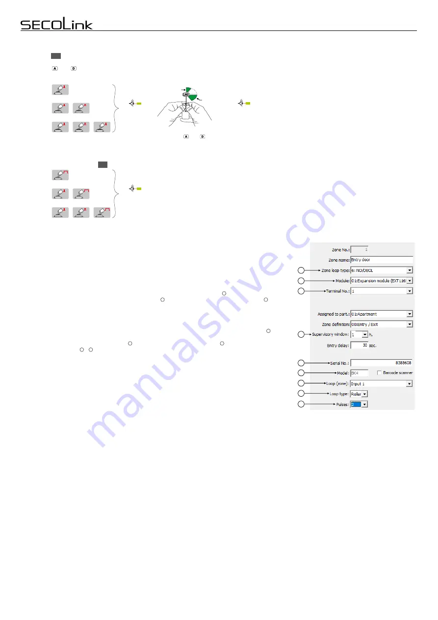
Enrollment using serial number is a two step process. First step requires entering the serial number and setting
up all necessary zone settings using the software MASCAD.
At t
he
second step the detector needs to be
triggered to send any signal to receiver. Both steps must be performed in order to complete the enrollment.
Step 1:
1. Connect the GSV4B to your computer using a USB cable.
2. Download project from GSV4B to software MASCAD (use the tab
Project data sending/receiving
).
3. Go to the tab
Zones.
4.
Enable the wireless zone by changing
Not used
loop type to any other loop type .
5. Wireless zone address consist from module address and wireless zone number in the module .
Note:
for
wireless zones
MA_1
– MA_8 the system will automatically assign
NO/DEOL
loop type and for wireless
zones
MA_9 – MA_16
the
Vibration
loop type. Don't change the loop type of a zone!
6. The wireless detector sends a supervision signal approximately every 1 hour. If the system does not receive
supervision (or alarm signal) signal from a specific detector, the detector is regarded as inactive. The
amount of time after which a transmitter is considered inactive is called the
Supervisory window
.
Note:
0
hours disables the supervision.
7. Enter
wireless detector serial numbe
r
.
S
oftware will identify the detector
and will guide to select all
necessary settings – . Do not forget to SAVE settings prior to uploading settings to the system.
8. Upload project to the system
(use the tab
Project data sending/receiving
).
9. Disconnect the USB cable.
Step 2:
1. To finish the enrolling procedure the detector must be triggered as many times as many it loops (zones) were
in use. It could be done by triggering the detector’s loop (zone) OR by pressing tamper switch.
To delete the wireless detector from the system just simply delete the detector serial number and upload the
modified project to the system.
1
2
3
4
5
6
7
9
R
Deleting the
remote control
Important:
all
remote controls
of selected user will be deleted
.
T
o select the user
press button
as many time as needed
and hold it on last digit until the
Status LED
switches On. Example of use:
S2
and so on ...
2nd user:
1st user:
S2
Hold
3rd user:
S2
S2
}
Hold
S2
S2
S2
}
Hold
}
Enrolling the remote control LT5
Use
utton
to select the user. Press once to select 1st user, press twice to select 2nd user and so on.
When user is selected the device will send a command to
b
S2
EXT116S
module to begin the process of enrolling
, the
Status LED
on GSV4B board will become On (solid). Take remote control LT5 and s
imultaneously hold down
the buttons
and
.
One Green color flash (~0,5 sec) followed by longer same color flash (~1 sec) indicates that LT5 is successfully enrolled.
When LT5 is
successfully enrolled the
Status LED
will start to flash GSM signal strength. Example of use:
S2
S2
1st user:
2nd user:
S2
3rd user:
Status LED
is On (solid)
and so on ...
Status LED
is flashing
}
}
Simultaneously hold down the
buttons and .
G
G
Green (1 sec)
Green (0,5 sec)
S2
S2
S2
}
}
}
Status LED
is On (solid)


