CQ7-A30
CQ7-A30 - Rev. First Edition: 1.0 - Last Edition: 2.0 - Author: S.B. - Reviewed by G.G. Copyright © 2016 SECO S.r.l.
55
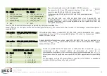
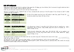
In order to avoid address conflicts, when both W83627DHG and XR28V384 are anabled, SW2 switches #2 and #4 must not be in the same position
at the same time (i.e, they must not be simultaneously ON or simultaneously OFF).
Only Qseven
®
modules offering LPC interface will be able to drive correctly the serial ports available on conenctors CN12.
Furthermore, it is necessary that the LPC SuperI/O is supported by module
’
s BIOS / BSP.
Finally, other two serial port interfaces are offered by the LPC SuperI/O
W83627DHG.
These serial ports are carried out externally through two dedicated RS-
232 transceiver, and are available on connector CN12, which is another
combo DB9 male + male connector, with the standard pinout shown in
the table on the left.
Please remember that the serial ports offered by the LPC-to-UART bridge XR28V384 and/or those offered by the LPC SuperI/O W83627DHG will be available only
in case that the Qseven
®
module used is able to manage these devices. It is also possible that the module used is able to manage both of them at the same time.
In order to avoid address conflicts between the two devices, it is available onboard a dedicated Dip Switch, SW2, for single device enabling/disabling and address
selection.
W83627DHG RS-232 COM port #1
connector - CN12
W83627DHG RS-232 COM port #2
connector - CN12
Pin Signal
Pin Signal
Pin Signal
Pin Signal
1
W_DCD_1#
6
W_DSR_1#
10
W_DCD_2#
15
W_DSR_2#
2
W_RxD_1
7
W_RTS_1#
11
W_RxD_2
16
W_RTS_2#
3
W_TxD_1
8
W_CTS_1#
12
W_TxD_2
17
W_CTS_2#
4
W_DTR_1#
9
W_RI_1#
13
W_DTR_2#
18
W_RI_2#
5
GND
14
GND
SW2 Switch
ON Position
OFF Position
1
W83627DHG enabled
W83627DHG disabled
2
W83627 at address 4Eh
W83627 at address 2Eh
3
XR28V384 enabled
XR28V384 disabled
4
XR28V384 at address 4Eh
XR28V384 at address 2Eh


