


CCOMe-965
CCOMe-965 - Rev. First Edition: 1.0 - Last Edition: 3.0 - Author: S.B. - Reviewed by G.G. Copyright © 2016 SECO S.r.l.
35
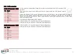
Signals carried to miniPCI-express slot #1 are the following:
P/PCIE_TX6-: PCI Express lane #6, Transmitting Output Differential pair.
P/PCIE_RX6-: PCI Express lane #6, Receiving Input Differential pair.
mPC / mPCIE_CLK1-: PCI Express Reference Clock for lane #6, Differential Pair.
USB5+ / USB5-: USB Port #5 differential pair.
PCIE_WAKE#: Board
’
s Wake Input, it must be externally driven by the miniPCI-e module
inserted in the slot when it requires waking up the system.
PCIE_RST#: Reset Signal that is sent from COM Express module to all PCI-e devices
available on the board.
mPCIE_CLOCK_REQUEST_1#: PCI Express Clock Request Input. This signal shall be driven
low by any module inserted in the miniPCI express slot, in order to ensure that the PCI-e clock
buffer available on the carrier board makes available the reference clock for the miniPCI-e slot.
SMB_CK: SM Bus control clock line for System Management, managed by the COM
Express module.
SMB_DAT: SM Bus control data line for System Management, managed by the COM
Express module.
On the slot #1 are also available the signals for interfacing to miniSIM cards, so that it is
possible to use miniPCI Express modems.
UIM_PWR: Power line for UIM module.
UIM_DATA: Bidirectional Data line between miniPCI-express card and UIM module.
UIM_CLK: Clock line, output from miniPCI-express card to the UIM module.
UIM_RESET: Reset signal line, sent from miniPCI-express card to the UIM module.
UIM_VPP: UIM Proprietary Use signal.
Please be aware that all signals related to User Identity Modules are managed directly by the
miniPCI-express card circuitry, they don
’
t involve neither carrier board
’
s nor COM Express
module
’
s management. The CCOMe-965 carrier board embeds only clamping diodes for
ESD protection on UIM signal and voltage lines.
Similarly to miniPCI-express slot #0 other three SMT RED LEDs are present near this Mini PCI-
Express Card Slot to show the presence of an eventual Wi-Fi PCI-Express Card inserted.
Green Led, D6: Wireless_WAN #1 present
Yellow Led, D5: Wireless_LAN #1 present
Red Led, D4: Wireless_PAN #1 present
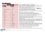
miniPCI-e Slot #1 - CN8
Pin Signal
Pin Signal
1
PCIE_WAKE#
2
+3.3V_A
3
N.C.
4
GND
5
N.C.
6
+1.5V_S
7
mPCIE_CLOCK_REQUEST_1#
8
UIM_PWR
9
GND
10
UIM_DATA
11
mPCIE_CLK1-
12
UIM_CLK
13
mPC
14
UIM_RESET
15
GND
16
UIM_VPP
17
N.C.
18
GND
19
N.C.
20
N.C.
21
GND
22
mPCIE_RST1#
23
PCIE_RX6-
24
+3.3V_A
25
P
26
GND
27
GND
28
+1.5V_S
29
GND
30
SMB_CLK
31
PCIE_TX6-
32
SMB_DAT
33
P
34
GND
35
GND
36
USB5-
37
GND
38
USB5+
39
+3.3V_A
40
GND
41
+3.3V_A
42
LED_WWAN1#
43
N.C.
44
LED_WLAN1#
45
N.C.
46
LED_WPAN1#
47
N.C.
48
+1.5V_S
49
N.C.
50
GND
51
N.C.
52
+3.3V_A


