background image

ENFORCER Hands-Free Video Door Phone 

SECO-LARM U.S.A., Inc. 

5


Installation – Camera: 

Installation – Additional Monitor: 


1.


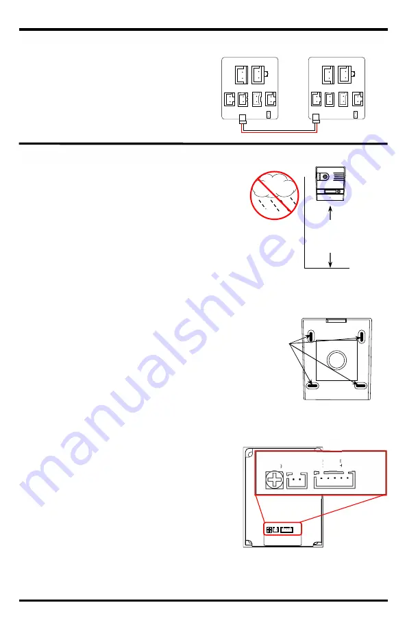
Position the camera so the area to be monitored is easily 
visible, typically 5ft (150cm) above the ground.  Do not 
position the camera in direct sunlight, or where it will be 
exposed directly to rain or snow. 

2.


Cut a hole large enough to run the minimum 21AWG  
2-conductor wire through the wall to where the camera unit 
is to be mounted.  If using a locking device, the wires used 
to control the device must also be run through this hole. 

3.


Run the 2-conductor wire from the camera location to 
where the primary monitor is mounted.  

Note: The distance between the camera and farthest 
monitor should not exceed 230ft (70m). If two cameras, 
measure from the farthest camera to the farthest 
monitor. 

4.


Using four of the included screws and four of the included 
screw anchors, attach the camera mounting bracket to the 
wall. 

5.


Run wires from the first two terminals on the left of the 
camera (+ and -) to the monitor's "CN 1" plug making sure 
to observe polarity. 

6.


If the color video door phone will be used to operate an 
electronic door strike or electromagnetic lock, connect the 
wires coming from the strike or lock to the relay 
connections on the back of the camera.  See the diagrams 
on pg. 7. 

7.


Plug the AC power adapter into a 120VAC socket. 

8.


Test the monitor and camera unit by pressing the doorbell 
button on the camera. The image in front of the camera 
should be displayed clearly. 

9.


To adjust the camera speaker volume, turn the 
potentiometer on the back of the camera clockwise or 
counterclockwise. 

10.


Push the tab on top of the bracket into the top of the 
camera. Make sure that no wires are pinched preventing 
the camera from sealing properly in the bracket.  

11.


Secure the camera to the mounting bracket with the 
included camera hex screws. 

If using a secondary monitor:


1.


Install the second monitor in the same way as the 
primary monitor (see pg. 4). 

2.


DP-264-M7Q: Run wire from the primary 
monitor’s "CN1A" plug to the secondary monitor’s 
"CN1" plug, making sure to observe polarity. 
Don't forget to adjust End-of-Line jumper 
accordingly. Please refer to pg. 4. 
 

5ft 

(150cm) 


Camera Mounting Bracket 


Use these 

holes to secure 

the bracket to 

the wall. 


Connection points and 

speaker adjustment 

Adjust the camera’s 
speaker volume by 
turning the 
potentiometer on the 
back of the unit. 


Volume  Power 

+  - 

E Lock 

N

C


C

O

M


N

O


CN1A 

CN1 

Connecting to DP-264-M7Q


(not included) 

Summary of Contents for SLI ENFORCER DP-264-1C7Q

Page 1: ...s gates etc from the monitor Easily connect additional monitors and an additional camera Simple 2 wire connection Built in microphone Adjustable color tone brightness speaker and ringer volume Camera and monitor turn off automatically when not in use Soft touch button operation Additional monitors and camera sold separately Up to 2 Cameras Up to 3 Monitors ...

Page 2: ...ation Primary Monitor 4 Installation Additional Monitors 5 Installation Camera 5 Operating Instructions 6 Wiring Diagrams 7 Troubleshooting 8 Note The distance between the camera and the farthest monitor should not exceed 230ft 70m Camera Type Color camera CMOS 1 3 CMOS sensor Resolution 700 TV lines Lens 2 1mm Relay output 3A 30VDC max dry contact Operating temperature 13 149 F 25 65 C Weight 1 l...

Page 3: ...onitor To bell To additional camera To additional monitor Jumper Front View Back View Ringtone volume adjustment Voice volume adjustment Chroma Contrast adjustment Brightness adjustment Interchangeable message holder 13 4 x7 16 44x11mm LEDs HD CMOS camera Camera speaker volume To primary monitor To locking devices Front View with sunshield Back View without sunshield Doorbell button Speaker Microp...

Page 4: ...housing If your installation has a single monitor the jumper must remain on the monitor If your installation has multiple monitors the jumper must remain in place on the monitor which is farthest from the camera but must be removed from the other monitors 1 The monitor must be positioned so that the image can be seen clearly and the user can operate the monitor s functions 2 Use the mounting brack...

Page 5: ...ic door strike or electromagnetic lock connect the wires coming from the strike or lock to the relay connections on the back of the camera See the diagrams on pg 7 7 Plug the AC power adapter into a 120VAC socket 8 Test the monitor and camera unit by pressing the doorbell button on the camera The image in front of the camera should be displayed clearly 9 To adjust the camera speaker volume turn th...

Page 6: ...ice is connected to the E Lock pressing the E Lock Button will allow access See the wiring diagram on pg 7 for more details Note The lock will only remain unlocked for 5 seconds after which the camera and monitor will turn off 4 To see what is going on at the entrance press the Monitor Button once to turn on the monitor The camera LED and monitor will automatically switch on but there will be no a...

Page 7: ...Door Fail Secure Release 13 8V E Lock Terminals SECO LARM SECO LARM Dry Contact Power Supply Maglock N C and COM Fail Safe Power Supply Plug in Harness Connections Bell CN5 Volume Power E Lock NC COM NO Monitor Additional Monitor Camera Additional Camera Volume Power E Lock NC COM NO Power CN3 1 2 CN1 Camera 1 2 Monitor CN1A 1 2 CN2 CN2A Additional Monitor Additional Camera Jumper Bell CN5 1 2 1 2...

Page 8: ... will not be held responsible for the use of this product in violation of any current laws or statutes FCC COMPLIANCE STATEMENT THIS DEVICE COMPLIES WITH PART 15 OF THE FCC RULES OPERATION IS SUBJECT TO THE FOLLOWING TWO CONDITIONS 1 THIS DEVICE MAY NOT CAUSE HARMFUL INTERFERENCE AND 2 THIS DEVICE MUST ACCEPT ANY INTERFERENCE RECEIVED INCLUDING INTERFERENCE THAT MAY CAUSE UNDESIRED OPERATION Notic...

Reviews: