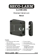
SECO-LARM Motorized Cabinet Lock
SECO-LARM U.S.A., Inc.
3
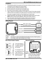
Wiring Diagram:
Installation:
Trimpot
Gently turn the trimpot on
the back of the lock body
from left to right to adjust
the relock time delay.
N.O COM N.C – +
2S
5S
1.
Find a suitable location for the cabinet lock. Ensure the lock body and rosette do not prevent
the drawer/door from opening and closing completely.
2.
Set relock time delay. See "Relock Time Delay" below.
3.
Wire the cabinet lock according to the wiring diagram below.
4.
Mount the lock body using the included 4 long wood screws.
5.
Apply a small piece of double-sided tape (not included) to the back of the rosette and gently
insert the pin into the receptacle on the lock body as to not lock the pin in place. Check that
the rosette is orientated correctly. See "Door Status Sensor Position" below.
6.
Close the drawer/door and open again. The rosette will be attached in the correct location.
NOTE:
If the pin becomes locked, trigger the relay control contact to unlock it.
7.
Secure the rosette to the drawer/door using the included 2 short wood screws.
8.
Test to ensure the rosette is aligned properly. Make adjustments as needed.
N
.O
C
O
M
N
.C
–
+
2
S
5
S
Wire Color
Function
Yellow
Bond sensor contact output (indicates locking element is in the "locked" position)
Blue
Door status contact output (indicates door is closed)
Red
Red
Power
Output #1
Lock status
Output #2
Door status
Relay control contact;
e.g., reader or switch
+
12~28
VAC/VDC
–
Yellow (N.C.)
Green (COM)
Blue (N.O.)
Door Status Sensor Position:
Relock Time Delay:
The sensor magnet on
the rosette should match
up with the sensor on
the lock body.
For installations where
the rosette faces the top
of the lock body, the
magnet and reed switch
should be adjacent.
NOTE:
Connected access control devices
must set time delay an additional
3sec longer than the Motorized
Cabinet Lock's relock time delay.


