background image

a`qSOMM rëÉê dìáÇÉ


29 

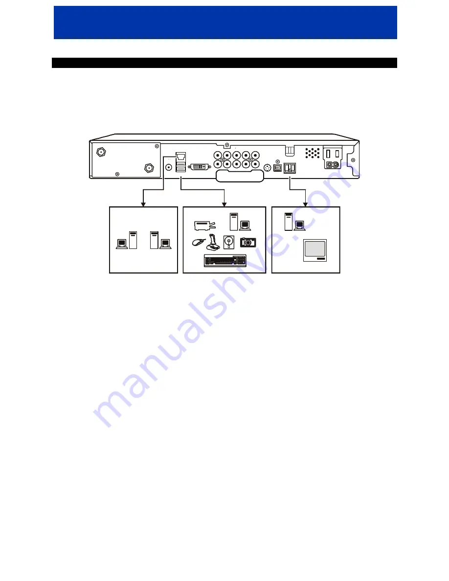
DATA DEVICES 

In addition to high quality audio and video, the DCT6200 has the capability to deliver high-speed data 
services such as Internet access, e-mail, IP Telephony, E-Commerce, and home banking.    

Your DCT6200 may be equipped with the interface connections illustrated, but their functionality depends 
on the services offered by your service provider. 

ETHERNET

USB

R

DVI D OUT

TO

TV/VCR

CABLE

IN

AUD O OUT

AUD O IN

TV

Pass Card

VIDEO

R

IN

L

OUT

S VIDEO

IEEE 1394

OPTICAL

SPDIF

SPDIF

Y

Pb

Pr

a`qSOMM

Home Ethernet

Network

USB

devices

Audio/Video

devices


Do not attempt to connect data devices without contacting your service provider. Advanced data features 
require the proper application and network infrastructure to operate. 


Summary of Contents for DCT 6200 HD

Page 1: ...able USB 1 1 VIDEO IN SMART CARD L AUDIO IN R INFO MENU POWER A B GUIDE SELECT interactive digital communications Digital Cable Box USER MANUAL DCT 6200 HD Wiring Instructions Additional Information Seaside TV ...

Page 2: ...erous voltage within the product s enclosure that may be of sufficient magnitude to constitute a risk of electric shock to persons The exclamation point within an equilateral triangle is intended to alert the user to the presence of important operating and maintenance servicing instructions in the literature accompanying the appliance CAUTION RISK OF ELECTRIC SHOCK DO NOT OPEN REFER SERVICING TO Q...

Page 3: ...g or similar surface Equipment should never be placed near or over a radiator or heat register or in a built in installation such as a bookcase or rack unless proper ventilation is provided 10 Power sources This product should be operated only from the type of power sources indicated on the mar king label If you are not sure of the type of power supplied to your home consult your local power compa...

Page 4: ...17 Object and liquid entry Never push objects of any kind into this equipment through openings as they may touch dangerous voltage points or short out parts that could result in a fire or electrical shock Never spill liquid of any kind on the product 18 Servicing Do not attempt to service this equipment yourself as opening or removing covers may expose you to dangerous voltage or other hazards ret...

Page 5: ...erference Causing Equipment Regulations Cet appareil numérique de la classe B respects toutes les exigences du Règlement sur le matériel brouilleur du Canada www ic gc ca eic site ic1 nsf eng home www ic gc ca eic site ic1 nsf fra accueil C A N A D I A N C O M P L I A N C E ...

Page 6: ...iconductor memories or other media Laws in the United States and other countries preserve for Motorola certain exclusive rights for copyrighted computer programs including but not limited to the exclusive right to copy or reproduce in any form the copyrighted computer program Accordingly any copyrighted Motorola computer programs contained in the Motorola products described in this manual may not ...

Page 7: ...r DCT6200 to a Standard Definition Stereo TV and Mono VCR 17 Connecting your DCT6200 to an A V Receiver Standard Definition TV and Stereo VCR 18 Connecting your DCT6200 to a Standard Definition Stereo TV Mono Stereo VCR and DVD 21 Setting Up Your New DCT6200 for Digital Cable Services 22 Activating Your DCT6200 22 Calling Your Cable Operator for Authorization 23 Optimizing Your HDTV Picture 24 Rec...

Page 8: ...2 Data Devices 29 User Options 30 Troubleshooting 32 ...

Page 9: ... programming Integrated high definition decoder with YPbPr component video output Digital Visual Interface DVI connector PCM AC 3 Dolby Digital and Dolby Pro Logic audio capability 54 860 MHz tuner Full feature access from front panel LED display with IR receiver for Seaside remote control The following items are included with your DCT6200 Seaside Universal Remote control with batteries Coaxial ca...

Page 10: ...o baseband video output of a VCR camcorder or other video device DVI TO TV VCR Connects DCT6200 to a high definition TV Connects to TV or VCR CABLE IN Connects to cable signal from your service provider IR Enables DCT6200 to control a VCR while recording a selected program Not supported by all program guides INFO MENU POWER CURSO R MSGS ON USB VIDEO IN L AUDIO IN R CURSOR Moves cursor around progr...

Page 11: ... VCR camcorder or other video device Delivers video to an external device such as a TV or VCR Y Pb Pr C Switched Outlet Delivers component video to an HDTV S Video Connect to S Video input of TV or VCR OPTICAL SPDIF Provides Dolby Digital 5 1 audio or PCM audio Connect AC power cord from another device such as a TV or VCR A B GUIDE SELECT C HANNEL SMART CARD REMOTE A B Display Displays channel num...

Page 12: ...C Functionality is determined by your service provider 11 NUMBER KEYS Use to directly select a channel 12 TV VCR BYPASS or A B Use to manually enable the RF bypass function Requires a cable ready TV to operate Not available on all units 13 STOP PAUSE PLAY REW RECORD F FWD Controls cable Video On Demand VOD VCR or DVD player 14 MUTE Toggles the sound on and off 15 LOCK PPV Use to limit viewing of s...

Page 13: ...onent video cable and left right audio cables are also provided to connect the DCT6200 to your TV If you are connecting a coaxial cable from the TO TV VCR connector on the DCT6200 to the coaxial CABLE ANTENNA IN connector on the TV you must tune your TV to channel 3 or 4 to view the DCT6200 output Connecting the DCT6200 in this manner will remove its high definition video output capability CAUTION...

Page 14: ... video S Video or composite video check the manual supplied with your TV to determine the best connection available High definition video can only be viewed with DVI IEEE 1394 or component video connections DVI IEEE 1394 and component video allow you to view both high definition HD and standard TV programming Composite video and RF coaxial connections allow you to view only standard definition TV ...

Page 15: ...has a DVI input connect to the DVI D connections on your DCT6200 instead of the component video connections Y Pb and Pr connectors For instructions on connecting for IEEE 1394 see Connecting your DCT6200 to an HDTV and D VHS on page 13 For the connections described on the following page you will need these cables RF 75 ohm supplied DVI or Component video supplied ...

Page 16: ... cable to the DVI D OUT connector on the DCT6200 and the DVI HDTV connector on your TV DVI HDTV HDTV DVI Cable Or Connect the component video cables to the Y Pb and Pr connectors on your DCT6200 and HDTV COMPONENT VIDEO INPUT Y Pb Pr HDTV AUDIO IN AUDIO OUT VIDEO R IN L OUT SPDIF Y Pb Pr Component Video Cable 3 Proceed to the instructions for Audio Connections ...

Page 17: ...ou will need the following cables Audio supplied To connect your audio connections for HDTV Connect the stereo audio cable to the AUDIO OUT R and L connectors on the DCT6200 and the AUDIO INPUT RIGHT and LEFT connectors on the HDTV AUDIO IN VIDEO R IN L OUT SPDIF Y Pb Pr AUDIO INPUT L R HDTV AUDIO OUT Stereo Audio Cable After you have finished connecting your DCT6200 see Setting Up Your New DCT620...

Page 18: ... Connect the optical SPDIF cable to the OPTICAL SPDIF connector on the DCT6200 and the OPTICAL connector on the A V receiver SPDIF Connect the digital audio cable to the SPDIF connector on the DCT6200 and the DIGITAL INPUT COAX connector on the A V receiver Stereo audio Connect the stereo audio cable to the AUDIO OUT R and L connectors on the DCT6200 and the AUDIO RIGHT and AUDIO LEFT connectors o...

Page 19: ... the CABLE IN connector on the DCT6200 2 Connect an IEEE 1394 cable to the IEEE 1394 connectors on your DCT6200 and D VHS digital VCR IEEE 1394 IEEE 1394 D VHS 3 Connect an IEEE 1394 cable to the IEEE 1394 connectors on your D VHS digital VCR and HDTV The IEEE 1394 is a video and audio connection so no audio connections are required if you are using the IEEE 1394 connection On screen graphics will...

Page 20: ... R and L connectors on the DCT6200 and the INPUT AUDIO RIGHT and LEFT connectors on the stereo TV Connect a video cable to the VIDEO OUT connector on the DCT6200 and the INPUT VIDEO on the TV or an S video cable to the S VIDEO connectors on the DCT6200 and the TV Stereo TV Either or S VIDEO CABLE ANTENNA IN VIDEO AUDIO LEFT AUDIO RIGHT INPUT AUDIO IN AUDIO OUT VIDEO R IN L OUT SPDIF Y Pb Video Cab...

Page 21: ...illustrated below 3 Connect a video cable to the VIDEO OUT connector on the DCT6200 and the INPUT VIDEO connector on the stereo VCR INPUT AUDIO L R VIDEO Stereo VCR AUDIO IN AUDIO OUT VIDEO R IN L OUT SPDIF Y Pb Video Cable Stereo Audio Cable 4 Connect a stereo audio cable to the OUTPUT AUDIO R and L connectors on the stereo VCR and the INPUT AUDIO RIGHT and LEFT connectors on the stereo TV as ill...

Page 22: ...hod doesn t support high definition video For more information see Connecting your DCT6200 to an HDTV on page 9 After you have finished connecting your DCT6200 see Setting Up Your New DCT6200 for Digital Cable Services on page 22 ...

Page 23: ...to the VIDEO OUT connector on the DCT6200 and the INPUT VIDEO connector on the VCR Mono VCR CABLE ANTENNA IN INPUT VIDEO VIDEO S VIDEO AUDIO IN VIDEO R IN L OUT SPDIF Y Pb r AUDIO OUT TO TV VCR CABLE IN RF Coaxial Cable Video Cable 4 Connect an RF coaxial cable to the TO TV connector on the VCR and the CABLE ANTENNA IN connector on the stereo TV Mono VCR Stereo TV TO TV CABLE ANTENNA IN RF Coaxial...

Page 24: ...efinition video For more information see Connecting your DCT6200 to an HDTV on page 9 For the connections described below you will need the following cables RF 75 ohm supplied Audio 3 one supplied two extra Video 4 To connect your DCT6200 to your A V receiver TV and stereo VCR first connect your DCT6200 to the A V receiver 1 Connect an RF coaxial cable to the cable wall outlet and the CABLE IN con...

Page 25: ...NPUT AUDIO R and L connectors on the A V receiver as shown below OUTPUT VCR INPUT VIDEO VIDEO AUDIO L R AUDIO L R Stereo VCR A V Receiver S VIDEO S VIDEO Stereo Audio Cable 6 Connect a video cable to the INPUT VIDEO connector on the stereo VCR and the VCR OUTPUT VIDEO connector on the A V receiver INPUT VCR OUTPUT VIDEO VIDEO AUDIO L R AUDIO L R Stereo VCR A V Receiver S VIDEO S VIDEO Video Cable ...

Page 26: ... video connector on the A V receiver and the INPUT VIDEO connector on the stereo TV TV MONITOR INPUT VIDEO AUDIO L R A V Receiver S VIDEO INPUT S VIDEO VIDEO Stereo TV Video Cable After you have finished connecting your DCT6200 see Setting Up Your New DCT6200 for Digital Cable Services on page 22 ...

Page 27: ...an RF coaxial cable to the TO TV VCR connector on the DCT6200 and the CABLE ANTENNA IN connector on the VCR 2 Connect an RF coaxial cable to the TO TV connector on the VCR and the CABLE ANTENNA IN connector on the stereo TV 3 Connect a stereo audio cable to the INPUT AUDIO RIGHT and LEFT connectors on the stereo TV and the AUDIO OUT ANALOG R and L connectors on the DVD 4 Connect a video cable to t...

Page 28: ...tertainment devices plug the power cord supplied with your DCT6200 into the DCT6200 power inlet and your wall outlet After a few moments HUNT appears in the front panel LED and then Fr 1 This indicates the DCT6200 is checking for a data channel with the information that allows it to synchronize with your cable operator s system and download software Until the data channel is identified HUNT Fr 2 H...

Page 29: ... beginning with GI The Unit Address consists of 16 numbers proceeded by UA 2 Turn on your DCT6200 by pressing POWER on the front panel 0 is displayed in the LED indicating the software download was successful and your DCT6200 is ready to be authorized for service 3 Call your cable operator Your cable operator will record your billing information and authorize your DCT6200 to operate on their syste...

Page 30: ...ED to view and change your settings Use your remote control or the cursor keys on the front panel to navigate the on screen display The key indicates the position of the cursor Press the and keys to highlight the setting you wish to change Press the key to select an option for that setting To exit the setting and move to another setting use the and keys To exit the menu and save your settings pres...

Page 31: ...he arrow key to select the 4 3 Override setting OFF Transmits standard definition TV programs using the picture resolution specified in YPbPr Output Type 480i Transmits standard definition TV programs in their original 480i format This is the default setting Some TVs cannot display 480i format on their component video inputs YPbPr Check your TV User Guide for more information Note If your DCT6200 ...

Page 32: ...UT AUDIO L R VIDEO OUTPUT AUDIO L R VIDEO s o Ls êÉÅÉáîÉê DIGITAL INPUT TV MONITOR OUTPUT SPEAKER CONNECTORS COAX VIDEO S VIDEO R DVD CABLE TV VIDEO 2 IN OUT VCR AUDIO VIDEO L VIDEO S VIDEO OPTICAL COAX DIGITAL ANALOG R L AUDIO OUT OPTICAL VIDEO S VIDEO VIDEO OUT asa píÉêÉç êÉÅÉáîÉê IN OUT TAPE 1 R CD IN AUX IN L SPEAKER CONNECTORS qs CABLE ANTENNA IN L R S VIDEO IN S VIDEO OUT VIDEO IN AUDIO IN A...

Page 33: ...audio levels on external devices such as your TV or A V Receiver Interactive Program Guide The interactive program guide IPG displays information about TV programs and enables you to access features such as Parental Control or Pay Per View Interactive program guides can vary with each cable service provider Refer to the interactive program guide instruction manual for detailed instructions On Scre...

Page 34: ...Press POWER or MENU to exit the on screen menu and save your selection Additional options are available for closed captions including font size colors and service selections See User Options at the back of this manual for more information on these options Overlaying graphics such as closed captions are not available on all DCT6200 YPbPr output setting and video output combinations If the DCT6200 i...

Page 35: ...ctions illustrated but their functionality depends on the services offered by your service provider ETHERNET USB R DVI D OUT TO TV VCR CABLE IN AUD O OUT AUD O IN TV Pass Card VIDEO R IN L OUT S VIDEO IEEE 1394 OPTICAL SPDIF SPDIF Y Pb Pr a qSOMM Home Ethernet Network USB devices Audio Video devices Do not attempt to connect data devices without contacting your service provider Advanced data featu...

Page 36: ... of the DCT6200 when it is tuned to 4 3 standard definition programs Defaults to 480i Options are OFF 480i or 480p If the YPbPr Output is set to 480i this setting becomes redundant and defaults to OFF This setting provides the ability to specify how 4 3 pictures are to be displayed on your TV Most TV programming is 4 3 aspect ratio square Selecting OFF will display regular TV programs that are 4 3...

Page 37: ... or CYAN Foreground Opacity Selects the opacity of the closed captions foreground Defaults to AUTO Options are AUTO TRANSPARENT TRANSLUCENT SOLID or FLASHING Background Color Selects the background color for closed captions Defaults to AUTO Options are AUTO WHITE BLACK RED GREEN BLUE YELLOW MAGENTA or CYAN Background Opacity Selects the background opacity for closed captions Defaults to AUTO Optio...

Page 38: ...nnels using the buttons on the DCT6200 front panel Check the batteries in the remote control Install new batteries if needed There is no audio when viewing cable channels Verify that the MUTE button on the DCT6200 or the remote control has not been pressed Press MUTE on the remote control to restore sound If the DCT6200 audio output is connected to the TV verify that the MUTE button on the TV has ...

Page 39: ...DCT6200 is connected to your VCR and you record programming using your VCR setting 4 3 Override to 480i will cause your VCR to record any graphic overlays program guides closed captions on screen menus that were displayed during the recorded program regardless of the YPbPr Output and video output combinations The 4 3 Override feature can be configured from the User Settings menu There are black ba...

Page 40: ... commercial or look for a graphic such as a network logo If the commercial fills the screen from top to bottom or the graphic appears below the active video the program is being letterboxed by the broadcaster You can minimize this by activating the zoom feature on the TV A broadcaster may include black bars on either side of a wide screen broadcast This is called a hybrid aspect ratio and results ...

Page 41: ...www seaside ns ca 539 6250 Office and Studio 1318 Grand Lake Road P O Box 4558 Reserve Mines N S B1E 1L2 ...

Reviews: