6.1
NOTE!
Illustrations hereafter are with a section of the trailing arm removed from the vehicle and are all "R" (offside) assembly. Refer to
manufacturer's service manual, or proprietary manual when using these instructions.
6.1.1
Clean the bore of pressed steel bush housing of any residual oil or grit. No lubricant or 'free release fluid' is to be present on the bush
sleeve or the housing bore.
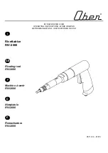
6.1.2
Place the new bush "Tee" plate inside the adaptor and locate the bush sleeve over reduced diameter and shoulder. It will only fit squarely
one way. The slots in the cylinder are offset about the axis, with the smallest adaptor segment the same side as the rivet stud shown in
(Fig.14). Clamp the depth control side legs (Fig.14) using the supplied M8 screws with a 6mm hexagon key. The legs should be
symmetrical about the fixing hole, but it is worth checking that there is equal projection to obtain even thrust. Check that the bush is
gripped and that datums (Fig.7) are clearly marked.
6.1.4
Place the 35mm 'C' ring on to the trailing arm (Fig.16), rotate the ring to clear the handbrake bracket. The four integral permanent magnets
will hold the ring in place.
6.1.5
Two people are now recommended, with one placing the adaptor and bush in (Fig.14) over the housing bore. See the orientation datums
for correct alignment (Fig.7). The second person can offer the press frame over the entire group of items shown in (Fig.16) ensuring the
bottom plate locates over the "C" ring. The second person can now wind in the thrust screw ensuring concentricity and squareness of
both the press and the adaptor. With a 16mm socket increase the torque and observe the bush sleeve progress through to correct depth
insertion. Excessive torque, above 180NM, is not envisaged, but if his occurs, stop and check alignments. Observe closely the depth
control legs, when they touch the trailing arm face resistance will increase abruptly, the bush is now fully inserted, see (Fig.15) telescopic
view.
DO NOT
attempt to tighten any further.
6.1.6
With possibility of heavy objects falling, special caution required whilst unscrewing the press and removing the entire kit.
6.1.7
Clean and lubricate before returning the kit to the carry case.
6.1.8
Refer to 5.1.1, 5.1.2 and manufacturer's or proprietary manual to refit the suspension, trailing arm, handbrake cable and return the vehicle
to the road for test drive.
6. INSERTING NEW BUSH
Depth
control
legs
Housing bush
orientation datums
from Fig.7
Trailing
Arm (Fig.1)
Adaptor
(rotate to clear "Tee" plate see 5.1.2)
New Bush Assembly
C/L
New Bush Assembly Insertion Details
Bottom Plate
Thrust Screw
Fig.14
Segment edge flush with
housing face, bush is
now inserted to correct depth.
7. MAINTENANCE
7.1
It is essential to keep the kit dry and free of swarf and grit. After use clean all components thoroughly ensuring thrust screw threads are
cleared with an air line, internal theads and external threads.
7.2
Inspect all components for signs of distortion, especially the screw threads and registration plate flatness. See warnings on torque,
misalignment and concentricity in operation, included to prevent damage.
7.3
Before returning the kit to the carry case smear blackened components and unpainted surfaces with an oiled cloth.
7.4
To avoid condensation store indoors with carry case closed.
NOTE:
It is our policy to continually improve products and as such we reserve the right to alter data, specifications and component parts without prior notice.
IMPORTANT:
No liability is accepted for incorrect use of this product.
WARRANTY:
Guarantee is 12 months from purchase date, proof of which will be required for any claim.
INFORMATION:
For a copy of our latest catalogue and promotions call us on 01284 757525 and leave your full name and address, including postcode.
New Bush Insertion Mode
35mm "C" Ring
Fig.15
Fig.16
Rivet
Stud
R
R
Top Plate