5.3.
Ignition system vacuum advance
5.3.1.
On standard points systems and some electronic ignition systems there are two types of advance methods used, both of which must
function correctly to obtain maximum performance and fuel economy.
5.3.2.
The first method Is Mechanical or Centrifugal, which operates by the use of weights located in the base of the distributor. The weights
move outwards advancing ignition timing as engine RPM increases. This is tested by firstly removing the vacuum advance line to disable
the system, then with a timing light connected, run the engine RPM up checking that the timing advances in accordance with the
manufacturer’s specification.
5.3.3.
The second method is Vacuum Advance, which senses engine load via manifold vacuum. A vacuum diaphragm is mounted onto the
distributor and connected to a rotating internal base plate which advances or retards timing as required to suit varying engine
loads. To test this system for correct operation, again with the timing light connected, raise the engine RPM and check timing advance
against manufacturer specifications. In the event that the vacuum advance is not operating, remove the vacuum line from the distributor
advance mechanism. Connect the VS402 (fig.2) and create a 5-10inHg vacuum, monitoring the timing at the same time. If a timing
advance is noted this confirms that the vacuum diaphragm and mechanical links are in order and that the fault is a vacuum supply. To
confirm this, connect the VS402 to the vacuum supply line and check the gauge reading. No vacuum should be noted at idle but when
the engine RPM is increased a vacuum increase should be observed. If this does not occur, trace the vacuum line back checking for
restrictions and breaks.
6. FUEL SYSTEMS
6.1.
Testing Mechanical Fuel Pumps
6.1.1.
The VS402 vacuum tester can be used to evaluate the condition of a mechanical fuel pump by testing the vacuum that it is able to
create. Locate and remove the suction line from the pump. Connect the VS402 vacuum tester to the suction port of the pump, start
and run the engine at idle. The vacuum reading that should be observed will vary slightly on different makes and models but as a general
rule approximately 15inHg of vacuum should be created. This should also be held for approximately 1 minute after engine shut down.
If this vacuum reading is not achieved or the vacuum drops off immediately with the engine shut down, the fuel pump requires either
overhaul or replacement.
6.2.
Carburettors
6.2.1.
There are many different types of vacuum control systems used on carburettors. Using the VS402 vacuum tester kit allows quick and
accurate testing of these systems. Listed below are just two examples of tests that can be carried out:
6.2.2.
Testing a Choke Break Diaphragm. With the engine at normal operating temperature but not running, disconnect the vacuum line to the
diaphragm module. Connect the VS402 vacuum tester (fig.3) and apply approximately 15inHg of vacuum and wait for 30 seconds.
No drop in gauge reading should be observed. With the vacuum still applied ensure that the choke butterfly is pulled to the fully open
position.
6.2.3.
Testing Vacuum Operated Carburettor Secondary Barrel. With the engine at normal operating temperature but not running, remove
the vacuum line from the secondary diaphragm module. Connect the VS402 vacuum tester (fig.4), hold the throttle and secondary air
valve flaps open. Operate the hand pump whilst observing free and easy opening of the secondary throttle butterfly.
6.3.
Testing Fuel Injection Pressure Regulator
6.3.1.
Multi-point fuel injection rail pressure must vary to suit changing engine loads and fuel delivery requirements. This is done using a
vacuum operated regulator which is connected to the engine manifold vacuum to sense the varying loads.
6.3.2.
To test the fuel rail pressure, a gauge is attached to the rail, then engine loads must be created to vary engine manifold vacuum. Simply
fig.3
fig.4
fig.2
V
S402.V3 | Issue - 1 14/09/16
Original Language Version
© Jack Sealey Limited
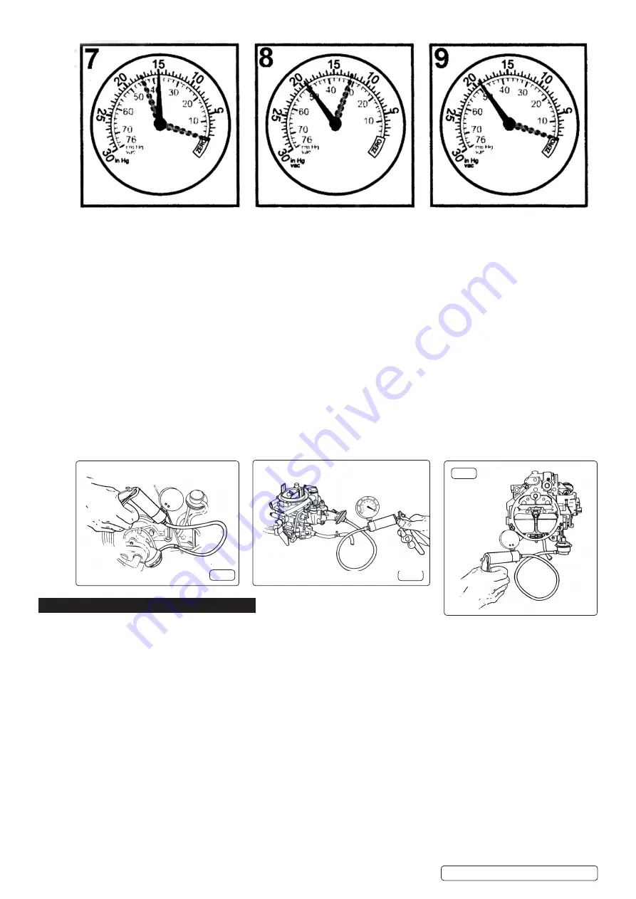
READING: Readings slightly lower
than for lower for normal engine
including when throttle is suddenly
opened then released.
CAUSE: Worn piston rings. Carry out
compression test.
READING: Regular drop between
normal and low reading.
CAUSE: Burnt valve.
R
EADING: Normal when first started
but drops rapidly when revs held at
3000rpm.
CAUSE: Restriction in exhaust system.


