


4. ASSEMBLY
!
WARNING! ENSURE THAT THE SAW IS NOT
CONNECTED TO THE MAINS POWER BEFORE
COMMENCING ASSEMBLY.
4.0.
Fixings.
Most of the saw is assembled using M6
nuts, bolts and washers. To tighten these fixings you
will need two 10mm spanners.
Unless otherwise stated, where the text refers to
‘a set of fixings’ this will mean
- 1 M6 x 16mm hex headed bolt
- 1 M6 flat washer (diameter 18mm)
- 1 M6 lock nut
4.1.
Saw stand.
The main saw stand will be assembled upside down on a suitable clean/flat surface. If necessary place some protective material down
first. Place the main table with the blade/motor box attached upside down on the surface so that there is room to subsequently fix
the table extension to it. The corners of the table are labelled 3,4,5 & 6 and these numbers will be matched to the corresponding
numbers on the legs.
Motor . . . . . . . . . . . . . . . . . . . . . . . . 2000W - 230V
Speed . . . . . . . . . . . . . . . . . . . . . . . . . . . . .2950rpm
Saw Blade . . . . . . . . . . . . . . . . .Ø315 x Ø30 x 3mm
Max. Depth of 90
O
Cut . . . . . . . . . . . . . . . . . .90mm
Max. Depth of 45
O
Cut . . . . . . . . . . . . . . . . . .60mm
Main Table . . . . . . . . . . . . . . . . . . . . .800 x 550mm
Output Table . . . . . . . . . . . . . . . . . . . .800 x 400mm
Dust Extraction Port . . . . . . . . . . . . . . . . . . .Ø28mm
3. SPECIFICATION
3.1.
Specification
leg 3
leg 4
leg 5
F
dust extraction
duct
leg strut
(long)
leg strut
(short)
leg 6
fig. 2
fig. 3
fig. 4
fig. 5
F
F
F
push
stick
hook
leg
leg
leg
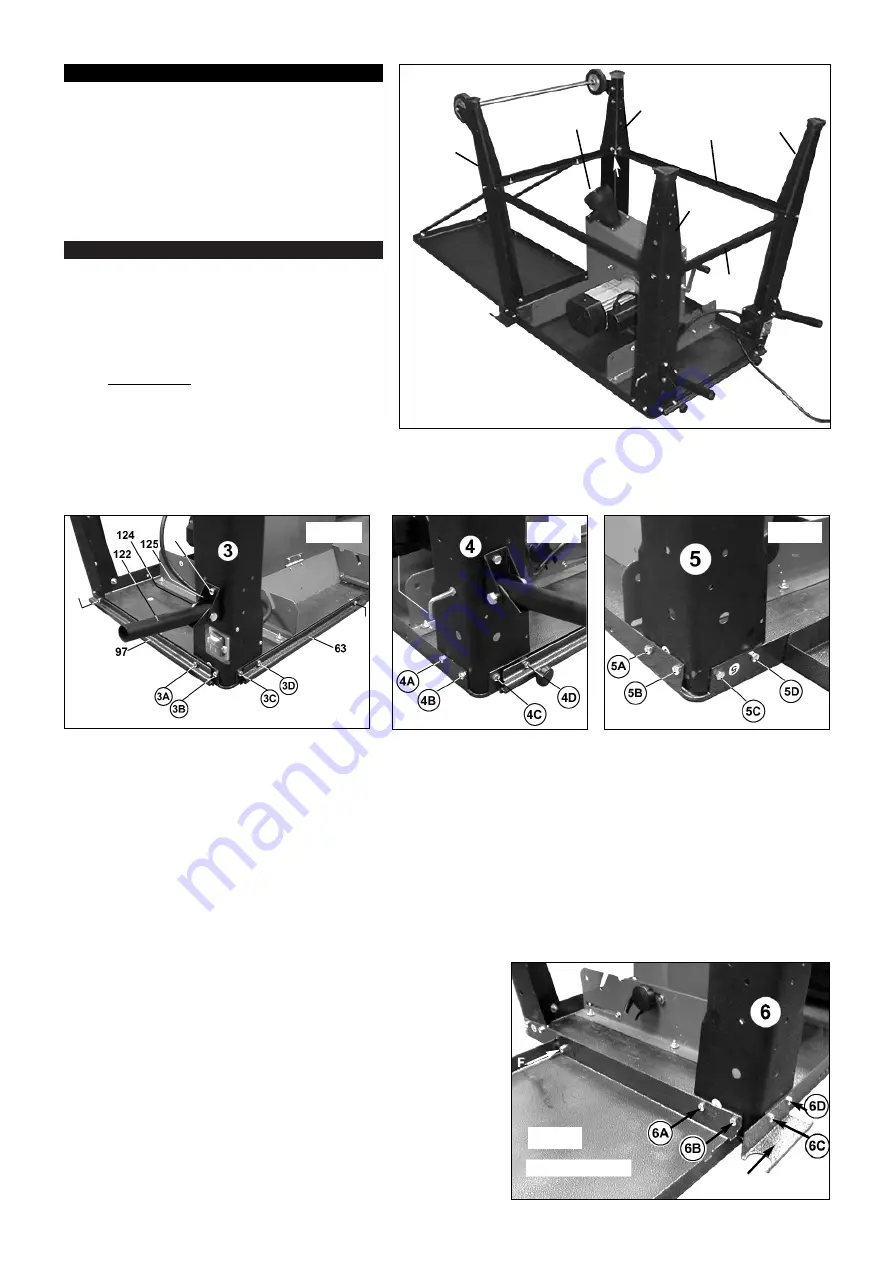
4.2
Match leg 3 to the corresponding numbered label attached to the side of the main table (See fig.3.) Use only sets of fixings at
positions 3A and 3B at this stage. The other two fixing points will be shared with the fence guides which are fitted later.
4.3
Mount the switch unit to leg 3 using two self tapping screws (ST4. 2x13mm as indicated at ‘A’ in fig.3).
4.4
Attach leg 4 as shown in fig.4. Use 3 sets of fixings at positions 4A, 4B & 4C at this stage.
4.5
Attach leg 5 as shown in fig.5 using 4 sets of fixings in positions 5A, 5B, 5C & 5D.
4.6
Attach leg 6 as shown in fig.6 using 2 sets of fixings at positions 6C & 6D. At the same time attach the dust extraction pipe bracket
which uses the same fixing positions. The other two fixing points will be shared with the table extension which is fitted later.
4.7
Assemble a short leg strut between legs 3 & 4 and between legs 5 & 6 using a single set of fixings at each end of each strut (see fig.2)
Ensure that the bent metal edges of the struts will be facing the floor when the unit is turned the right way up.
4.8
Assemble a long leg strut between legs 3 & 5 and between legs 4 & 6 using a single set of fixings at each end of each strut (see fig.2)
Ensure that the bent metal edges of the struts will be facing the floor when the unit is turned the right way up.
4.9
Where the struts overlap each other on the inside of each leg (four places) bolt them together with a single set of fixings. (See ‘F’ in fig.2)
4.10
If required, extend the length of the table by bolting the table extension to the end of the main table as shown in fig.2 & 6. The extension
is offset towards leg 6 and shares two of the leg fixings. Use 3 sets of fixings in positions 6A, 6B and at position ‘F’ as shown in fig.6.
4.11
Attach the two bracing struts between the outer edge of the extension and the adjacent leg cross brace as shown in fig.2. Use a single
set of fixings at each end of each strut.
4.12
Attach fence guide (97) to the front table edge between legs 3 &
4 using two brackets (98) and supplied screw fixings etc.
4.13
Attach the sliding guide (63) to the long side of the table edge
adjacent to the switch leg using supplied nuts and bolts etc.
4.14
Attach the dust extraction duct (part no.38) to the lower face of the red box
enclosing the blade using 4 bolts M4 x 12mm. See fig.2.
fig. 6
leg
table extension
dust extraction
pipe bracket


