


4. PREPARING INVERTER FOR USE
3. CONTROLS
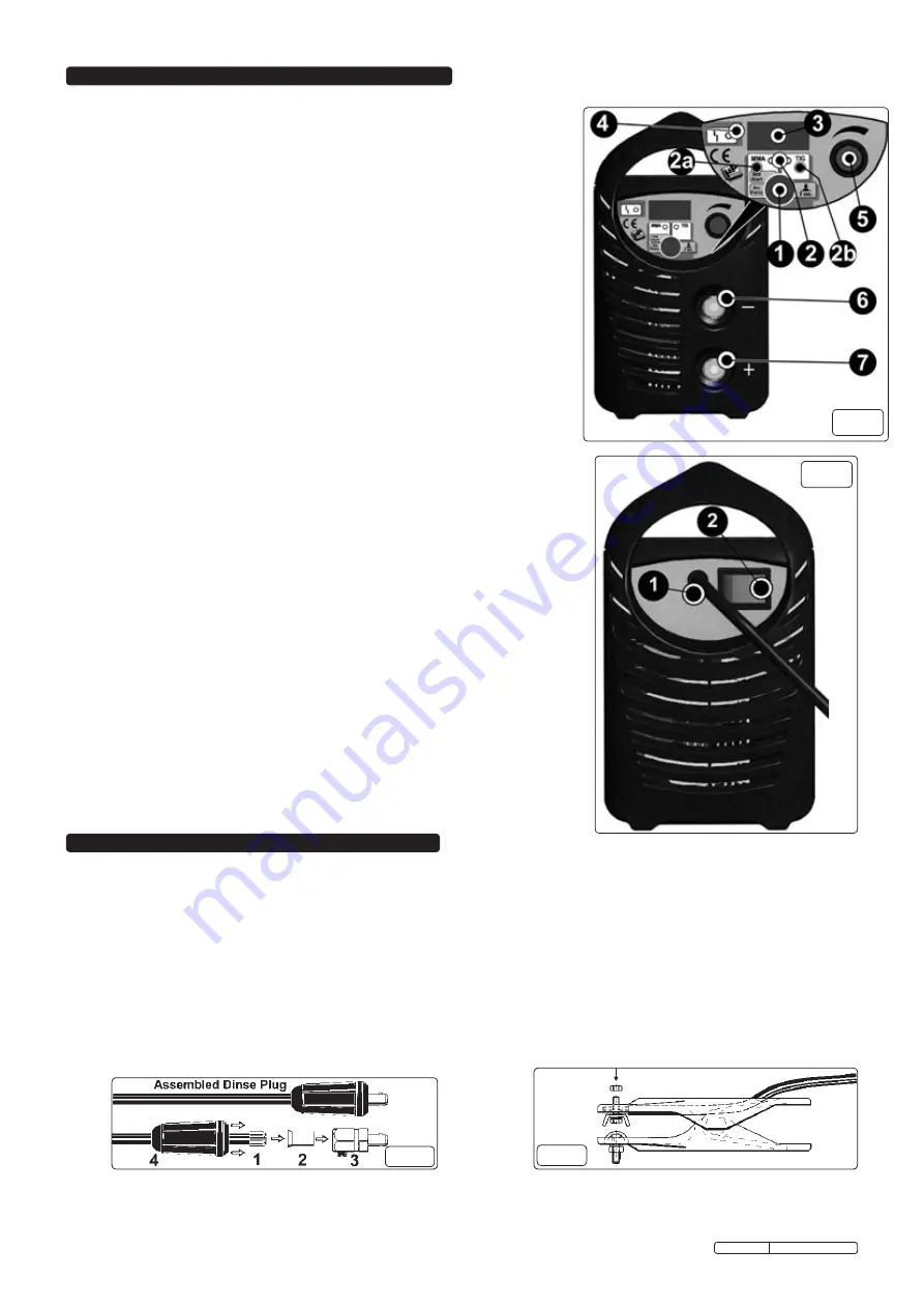
3.1 FRONT PANEL LAYOUT (refer to Figure 2).
1.
OPERATING MODES AND PARAMETERS BUTTON.
Primary function.
MMA or TIG selection.
Secondary function (press and hold in MMA mode).
Hot Start and Arc Force
.
Rapid press and release of the button allows parameter selection to be controlled by the
Encoder (5) with the relative value displayed on the Alphanumeric display (3). Press and hold
the button to exit this settings procedure.
Hot Start ('hot XX' on the display).
Initial overcurrent regulator setting (from 0-100%) with the percentage increase compared to
the preset welding current value indicated on the display. This setting facilitates the striking of
the electric arc.
Arc Force ('arc XX' on the display).
Dynamic overcurrent regulator setting (from 0-100%) with the percentage increase compared
to the preset welding current value indicated on the display. This setting improves welding
fluidity and prevents the electrode from sticking to the workpiece.
2.
OPERATING MODE AND PARAMETER SETTING LEDs.
2a. Fixed LED.
MMA mode enabled.
Flashing LED
. Arc Force or Hot Start enabled.
2b. Fixed LED.
TIG mode enabled.
3.
ALPHANUMERIC DISPLAY.
4.
YELLOW LED.
OFF by default, when LED is illuminated this indicates that the machine is blocked after one
of the following protection devices has been triggered:
Thermal Relay.
The temperature inside the welding machine is too high. The machine resets
its standard default settings automatically.
'AL2'
alarm on the display.
Line overvoltage and undervoltage safeguard.
If the voltage is +/-15% higher or lower than
the rated value.
'AL1'
alarm on the display.
ANTI STICK protection.
The electrode is stuck to the workpiece and requires manual
removal. The welding machine resets its standard default setting automatically.
5.
ENCODER.
Adjusts the welding settings. Adjustments can also be carried out whilst welding operations
are in progress.
6.
DINSE SOCKET
(negative
-
). For the connection of a welding cable Dinse plug.
7.
DINSE SOCKET
(positive
+
). For the connection of a welding cable Dinse plug.
3.2 REAR PANEL LAYOUT (refer to Figure 3).
1.
MAINS CABLE.
2.
MAIN ON/OFF SWITCH
(Illuminated).
Fig 4
Fig 5
4.1
CONNECTION TO THE MAINS.
The unit is fitted with a 13Amp plug and is designed to operate in both welding modes on a 13Amp supply. If
however the unit is used consistently at high output, connection to a 30Amp supply may be considered. Seek the advice of a qualified
electrician on connection to a suitable supply.
4.2
WELDING CABLE CONNECTIONS.
The torch cable is supplied ready assembled but it may be necessary for you to assemble the work clamp cable.
Attach the work clamp to one end of the cable as shown in fig.5. To connect the Dinse Plug as shown in fig.4 first thread the cable through the outer
cover of the plug (see fig.4 - 4). Now remove 20mm of insulation sheath from the end of the cable and fold back the copper wire all around the outside of
the sheath (1). Push the cable end into the copper sleeve (2) so that the folded back wire makes good contact with the inside of the sleeve. Push the
copper sleeve into the brass plug body (3) and tighten the large grub screw until the cable is firmly held. Now slide the outer plug cover up the cable and
press the brass body into it as shown in fig.4.
Original Language Version
TIG150T Issue: 1 - 11/11/11
fig 3
fig 2


