


4.1.2
Power Output switch.
Set the switch to position 1 or 2 for welding
up to 2mm thickness. Use settings 3,4,5,6. for thicker welds.
4.1.3 S
etting the welder controls.
In principle, the lower the amperage
required, the slower the wire speed. See setting chart below for
voltage and corresponding wire speeds. Note: these settings are only
a guide and will vary according to the operator's experience.
4.1.4
Welding mild steel.
To weld mild steel you can use CO² gas for most tasks where spatter
and the high build up of weld do not pose a problem. Welding with a
long arc reduces penetration and widens the arc. This in turn results
in more spatter. A long welding arc can be appropriate for welding butt
joints in thin materials. Welding with a short arc, at the same weld
settings, results in greater penetration and a narrower weld and
reduces the amount of spatter. To achieve a consistent spatter free
and flat weld, you must use an Argon/CO² mixture.
4.1.5
To weld aluminium use:
Argon gas,
0.8mm Contact Tip,
0.8mm Aluminium Wire,
4.1.6
Overload Protection.
Thermostatic overload protection is provided.
When an overload has occurred, leave the unit to cool. The
thermostat will automatically reset the unit when the temperature has
returned within limits
4.1.7
Spot Welding.
Spot welding may be carried out as shown in fig.16.
It will be necessary to fit a spot welding gas cup.
(a) Overlapping metal sheets with a
maximum thickness of 0.8 mm may be
welded as indicated.
(b) Alternatively they may be welded
edge to surface as indicated.
(c) For thicker sheet pre drilled holes
holes may be employed.
4.1.8 Use the wire feed control in conjunction
with the spot weld timer beside it. To
activate the timer turn the knob clockwise.
The settings indicated in the black portion
of the chart are for guidance only and
may vary with operators experience.
6.1.
WIRE FEED UNIT
Check the wire feed unit at regular intervals. The feed roller wire guide plays an important part in obtaining consistent results. Poor
wire feed affects welding. Clean the rollers weekly, especially the feed roller groove, removing all dust deposits.
6.2.
TORCH
Protect the torch cable assembly from mechanical wear. Clean the liner from the machine forwards by using compressed air. If the liner is
clogged it must be replaced.
6.3.
CHANGING FEED ROLLER
(See Section 3.12)
6.4.
CONTACT TIP
The contact tip is a consumable item and must be replaced when the hole becomes enlarged or oval. The contact tip MUST be kept free
from spatter to ensure an unimpeded flow of gas. Refer to fig.11 and section 3.9 for removal and replacement.
6.5.
GAS CUP
The gas cup must also be kept clean and free from spatter. Build up of spatter inside the gas cup can cause a short circuit at the contact tip
which will result in either the fuse blowing on the printed circuit card, or expensive machine repairs. To keep the contact tip free from spatter, we
recommend the use of Sealey anti-spatter spray (MIG/722308) available from your Sealey Dealer. Refer to fig.12 and section 3.9 for removal and
replacement.
6.6.
REPLACING THE LINER
Wind the wire back on to the spool and secure it. Unscrew the torch from the machine and undo the brass nut. The liner should
now be visible. Pull it out and replace with a new one.
6. MAINTENANCE
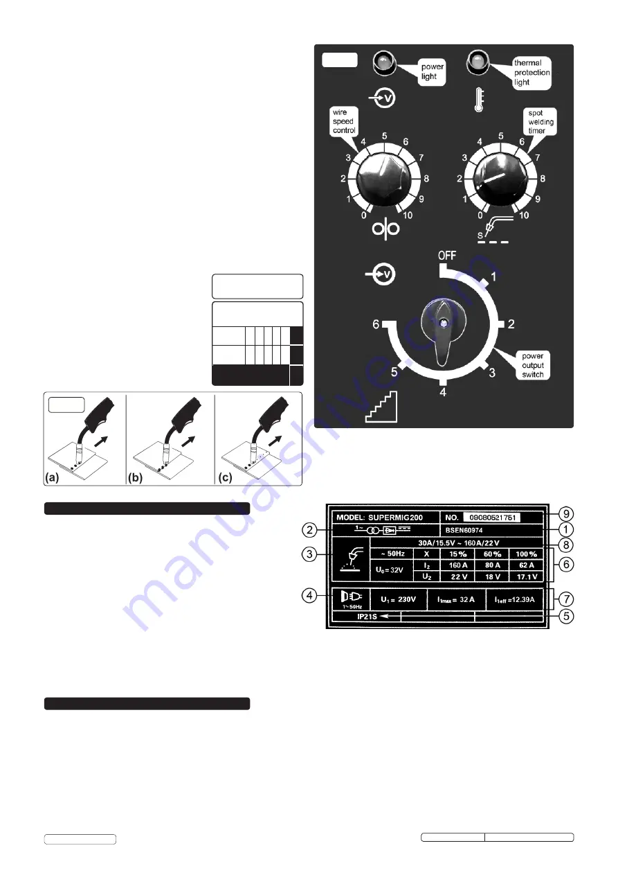
On the front of the welder is the ratings plate, giving the
following data:
1 -
The standard relating to the safety and construction
of arc welding and associated equipment.
2
- Single phase transformer - rectifier.
3 -
Welding with a continuous flow of welding wire.
4 -
Single-phase AC supply.
5 -
Rating of internal protection provided by casing.
6 -
Output
U0: Rated minimum & maximum no load voltage.
I2, U2: Current and corresponding voltage.
X: Welding ratio based on a 10 minute cycle. 20% indicates 2 minutes welding and 8 minutes rest, 100% indicates continuous welding.
7 -
Mains Supply U1: Rated supply voltage and frequency. Imax: Maximum current.
I1eff: Maximum effective current.
8 -
Welding current range.
9 -
Serial Number. Specifically identifies each welder.
5. RATINGS PLATE
Wire 0.6mm Steel
Argon / CO² Mix
Voltage
Step:
1 2 3 4 5
6
Wire
Speed:
5 6 7 8 9
10
SETTINGS SHOWN
AS GUIDE ONLY
Spot Welding Timer
6
6
10
fig.15
fig.16
Original Language Version
SUPERMIG200 Issue No: 3 (I) - 06/03/14
© Jack Sealey Limited


