


6. 1. Wire feed unit
Check the wire feed unit at regular intervals. The feed roller wire guide plays an important part in obtaining consistent results. Poor wire
feeding affects welding. Clean the rollers weekly especially the feed roller groove removing all dust deposits.
6. 2. Torch
Protect the torch cable assembly from mechanical wear. Clean the liner from the machine forwards by using compressed air. If the liner
is clogged it must be replaced.
6. 3. Contact Tip
(to remove tip follow steps in 3.3.6. and to replace 3.3.9. a & b very carefully).
The contact tip is a consumable item and must be replaced when the hole becomes enlarged or oval. The contact tip
MUST
be kept free from
spatter to ensure an unimpeded flow of gas.
6. 4. Gas Cup (or nozzle).
(to remove cup follow steps in 3.3.6. and to replace 3.3.9. a & b very carefully).
The gas cup must also be kept clean and free from spatter. Build up of spatter inside the gas cup can cause a short circuit at the contact tip
which will result in either the fuse blowing on the printed circuit card, or expensive machine repairs. To keep the contact tip free from spatter
we recommend the use of Sealey anti-spatter spray (MIG/722307) available from your Sealey Dealer.
6. 5. Replacing the Liner
Wind the wire back on to the spool and secure it. Unscrew the torch from the machine and undo the brass nut. The liner should now be
visible. Pull it out and replace with a new one.
6. 6. Changing Fuses (
The fuse is located on the circuit board).
A fuse is mainly blown for the following reasons:
3
Spatter collecting in the gas cup causing contact tip to short circuit.
3
Wire tension is too great.
3
A sudden surge of current.
6. 7. Changing Feed Roller
IMPORTANT:
if necessary adjust the feed roller to the corresponding wire size by turning the roller around.
There are two grooves on the feed roller, 0.6mm and 0.8mm. Always use the groove on the outside of the roller, (the groove nearest to you).
To remove the feed roller, undo the hex nut and remove. Clean and turn, or if damaged change the feed roller.
6. 8. Electrical Safety
For full compliance with current legislation electrical integrity checks must the undertaken by a qualified competent person. See chapter 1
electrical safety.
6.
MAINTENANCE
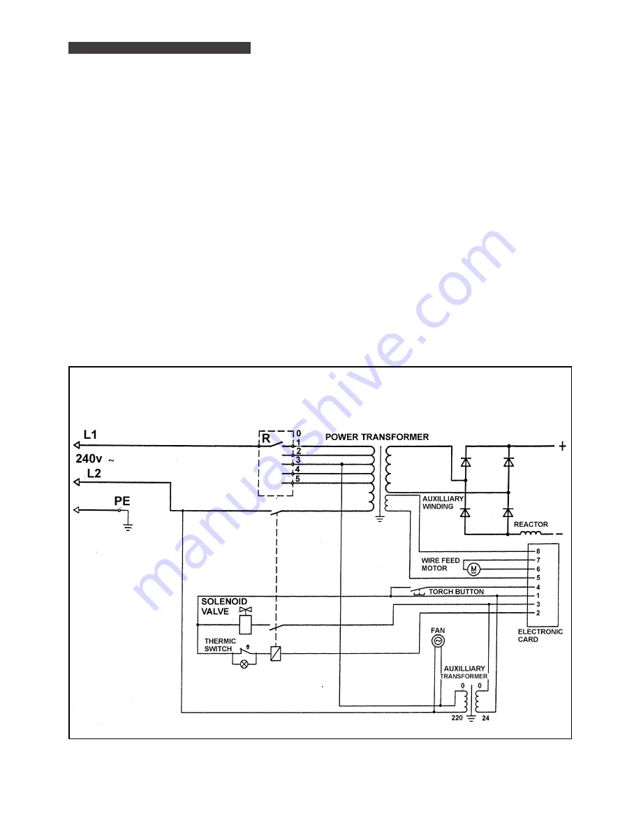
250/10 WIRING DIAGRAM
SUPERMIG 250-Job181-280198


