


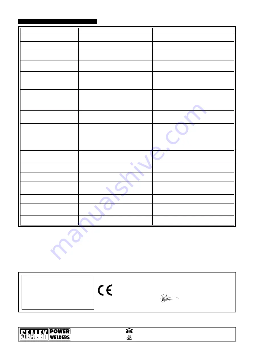
1. Power source stops
2. No weld current, fuse blowing in 13amp plug
3. No weld current
4. Feed motor not working, lamp is on
5. Wire does not feed, feed roller rotates
6. Wire feeds unevenly.
7. Unstable arc.
8. Porous weld
9. Electrode sticking in contact tip or gas cup
(nozzle)
10. Irregular weld head
11. Weld bead too narrow and raised
12. Weld bead too wide
13. Poor penetration
14. Excessive penetration
15. Fuse blowing
Overheating protection activated due to overload
Rectifier blown
Bad connection between clamp & workpiece
Break in earth lead
Break in torch lead
Fuse blown
Gear damaged or worn
Motor defective
Pressure roller improperly adjusted
Dirt, copper, dust, etc, have collection in torch liner
Gas cup (Nozzle) defective
Deformed wire
Dirt, etc, in liner
Gas cup (Nozzle) or contact tip defective
Gas cup (Nozzle) spattered
Feed roller groove clogged
Feed roller groove deformed
Wrong tension
Incorrect settings
Impurities in weld area
Worn or defective gas cup (nozzle)
No gas
Gas cup clogged
Draft blowing away shielding gas
Rusty or dirty joints
Torch too far from or at wrong angle to work
Gas leak
Worn or defective gas cup (nozzle)
Electrode deformed
Wire speed too slow
Torch incorrectly held
Wire weaving in weld pool
Weld current too high
Weld speed too low
Weld current too high
Weld speed too low
Arc too long
Weld current too high
Arc too long
Weld current too high
weld speed too slow
incorrect distance of torch to workpiece
Tension too great
Gas cup contact tip clogged
PROBLEM
POSSIBLE CAUSE
REMEDY
(Numbers refer to chapter and item heading)
7. TROUBLESHOOTING
Protection automatically resets when transformer has cooled
(about 15 min).
Replace rectifier.
Clean or grind contact surface and weld area.
Repair or replace earth lead.
Repair or replace torch.
Replace fuse 1.5 amp.
Replace gears.
Replace motor (Contact service agent).
Adjust tension. (Chapter 3).
Clean the liner from the machine forward. Use compressed air.
If too much dirt, replace the liner. (Chapter 6).
Replace gas cup (nozzle) and check tip. (Chapter 4 & 6).
Check pressure roller tension & adjust if necessary (Chtr 6).
Clean the liner from the machine forward. Use compressed air.
Replace gas cup (nozzle) or contact tip (Chapter 6).
Clean or replace gas cup (nozzle). (Chapter 6).
Clean feed roller. (Chapter 6).
Replace feed roller. (Chapter 6).
Adjust tension. (Chapter 3).
Use recommended settings. (Chapter 4).
Clean or grind weld area. (Chapter 4).
Replace gas cup (nozzle) and check tip. (Chapter 6).
Open gas cylinder, regulate gas flow.
Clean or replace cup. (Chapter 6.).
Screen off welding site or increase gas flow.
Clean or grind. (Chapter 4).
The distance from gas cup to workpiece should be 8-10mm
and torch angle 60
0
.
Check hoses, connections and torch assembly. (Chapter 6).
Press the gas cup in correction position.
Replace gas cup (nozzle). (Chapter 6).
Check pressure roller tension. (Chapter3. & Chapter 6).
See recommendations for wire speed. (Chapter 4).
Use torch angle 60
0
. (Chapter 5).
Check pressure roller tension & adjust as needed. (Chapter 3).
Increase voltage and wire speed. (Chapter 4).
Move torch slower and weave a little more.
Decrease voltage and wire speed. (Chapter 4).
Move torch faster and weave less.
Bring torch closer to workpiece.
Increase voltage and wire speed. (Chapter 4).
Bring torch closer to workpiece.
Decrease voltage and wire speed. (Chapter 4).
Move torch faster.
Torch distance should be 8-10mm. (Chapter 5).
Release tension. (Chapter3.).
Clean gas cup and contact tip. (Chapter 6).
NOTE:
It is our policy to continually improve products and as such we reserve the right to alter data, specifications and component parts without prior notice.
IMPORTANT:
No liability is accepted for incorrect use of product.
WARRANTY:
Guarantee is 12 months from purchase date, proof of which will be required
for any claim.
INFORMATION:
Call us for a copy of our latest catalogue on 01284 757525 and leave your full name and address including your postcode.
01284 757500
01284 703534
E-mail:
Sole UK Distributor
Sealey Group,
Bury St. Edmunds, Suffolk.
Web address: www.sealey.co.uk
Declaration of Conformity
We, the sole importer into the UK, declare that the
product listed below
is
in conformity with the following EEC standards and directives.
The construction file for th
is
product
is
held by the Manufacturer and may
be inspected by a national authority by contacting Jack Sealey Ltd
For Jack Sealey Ltd. Sole importer into the UK of Sealey
as Power Welders
25th September 2002
Signed by Mark Sweetman
Model:
SUPERMIG150/5.V2
73.23/EEC
Low Voltage Directive (S.I. 1994/3260)
89/336/EEC
EMC Directive (S.I. 1992/2372 &
Amendments).
SUPERMIG150/5.V2 - (1) - 241002


