


NOTE:
Dampen the sponge wiper before using the soldering station.
4.1. Connection
4.1.1. Push the DIN plug attached to the iron lead into the socket on the front panel of the control unit (fig.1).
4.1.2. Push the power cord into the socket at the rear of the control unit, after ensuring that the power supply is to the correct standard.
4.2.
Switching On
4.2.1.
Switch the on/off switch to the ‘
.
’ setting.
4.2.2. The display will show ‘80’ briefly, denoting the model number.
4.2.3. The last temperature set will be displayed for 3 seconds.
4.2.4. After a further 3 seconds, the display will show the real-time temperature of the tip.
NOTE:
The number of bars shown by the analogue current display (fig.1.7) represent the current being applied to the tip.
4.3.
Temperature Setting
4.3.1. The default temperatures stored by buttons: 1, 2 and 3 are 200,300 and 400°C respectively.
4.3.2. With the normal settings applied, the temperature can be adjusted by means of the ▲ and▼ buttons (fig.1).
4.3.3. The display will go to ‘set’ and the required temperature will either increase or decrease. Holding the button down will allow rapid
adjustment.
4.3.4. When the button is released, the display will revert to ‘real’ to illustrate the current temperature.
4.3.5. To store a required temperature, set as in 4.3.1., then hold one of the the preset buttons down for 3 seconds. The new temperature will
then become the stored value assigned to that button.
4.3.6. The default temperature setting is in 5°C graduations. For finer adjustment see
section 4.7.
4.4.
Locking the Keypad
4.4.1 The keypad may be locked by pressing all three preset buttons simultaneously for 3 seconds.
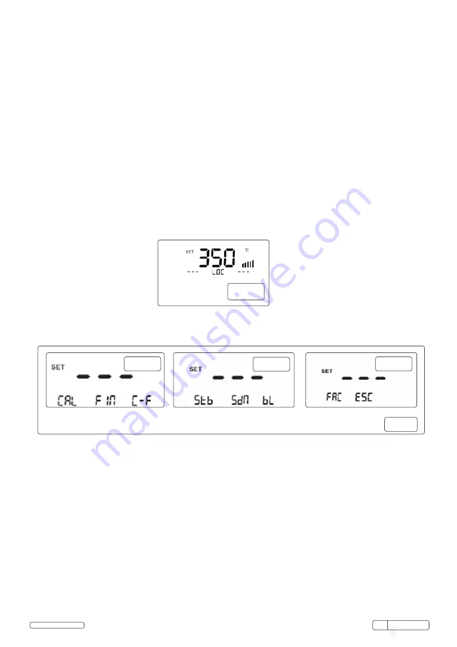
4.4.2. The display will show ‘loc’ (fig.3) and none of the buttons will function.
4.4.3. To unlock the keypad, press all three keys again for 3 seconds; the display and button functions will revert to normal.
4.5.
System Setting
4.5.1. To access the system setting pages, press ▲ and▼ buttons simultaneously for 3 seconds. This will display page 1 of the systems menu
(fig.4).
4.5.2. To scroll between system setting pages, use the ▲ and▼ buttons. Each click of the ▼ button advances by one page, and vice versa.
fig.3
page 1
page 2
page 3
fig.4
4.6.
Calibration
4.6.1. To access the system setting pages, press ▲ and▼ buttons simultaneously for 3 seconds.
4.6.2.
To start calibration: press ‘1’ on page1. ‘CAL’ will flash.
4.6.3. Ensure that the tip of the soldering iron is well tinned with solder to disperse the heat.
4.6.4. Measure the tip temperature (T1) and compare with the reading (T2).
4.6.5. If T1 exceeds T2, press ▲ until the difference is displayed. If T2 exceeds T1, press▼ until the difference is displayed.
E.G:
If measured temperature(T1) is 350°, and display (T2) shows 370°, the display will need reducing by 20°. Scroll will the ▼ button
until -20° is reached.
4.6.6. Press button ‘1’ to save the setting.
4.7.
Fine Temperature Adjustment
4.7.1
.
To access the system setting pages, press ▲ and▼ buttons simultaneously for 3 seconds.
4.7.2
.
To access the system setting pages, press ▲ and▼ buttons simultaneously for 3 seconds.
4.7.3. To alter the temperature adjustment between 5° and 1° increments: press ‘2’ on page1. ‘Fin’ will flash.
4.7.4. Scroll between ‘Off’ (5°) and ‘On’ (1°) by means of the ▲ and▼ buttons.
4.7.5. Press button ‘2’ to save the setting.
4.8.
Temperature Scale Selection
4.8.1. To access the system setting pages, press ▲ and▼ buttons simultaneously for 3 seconds.
4.8.2. To switch between Celsius and Fahrenheit scales: press ‘3’ on page 1.’C-F’ will flash.
4.8.3. Toggle either the ▲ and▼ button to change from C to F and back.
4.8.4. Press button ‘3’ to save the change.
ST80 Issue:1 31/03/15
© Jack Sealey Limited
Original Language Version
Page Functions


