background image

4.2.    MAIN PARTS DESCRIPTION

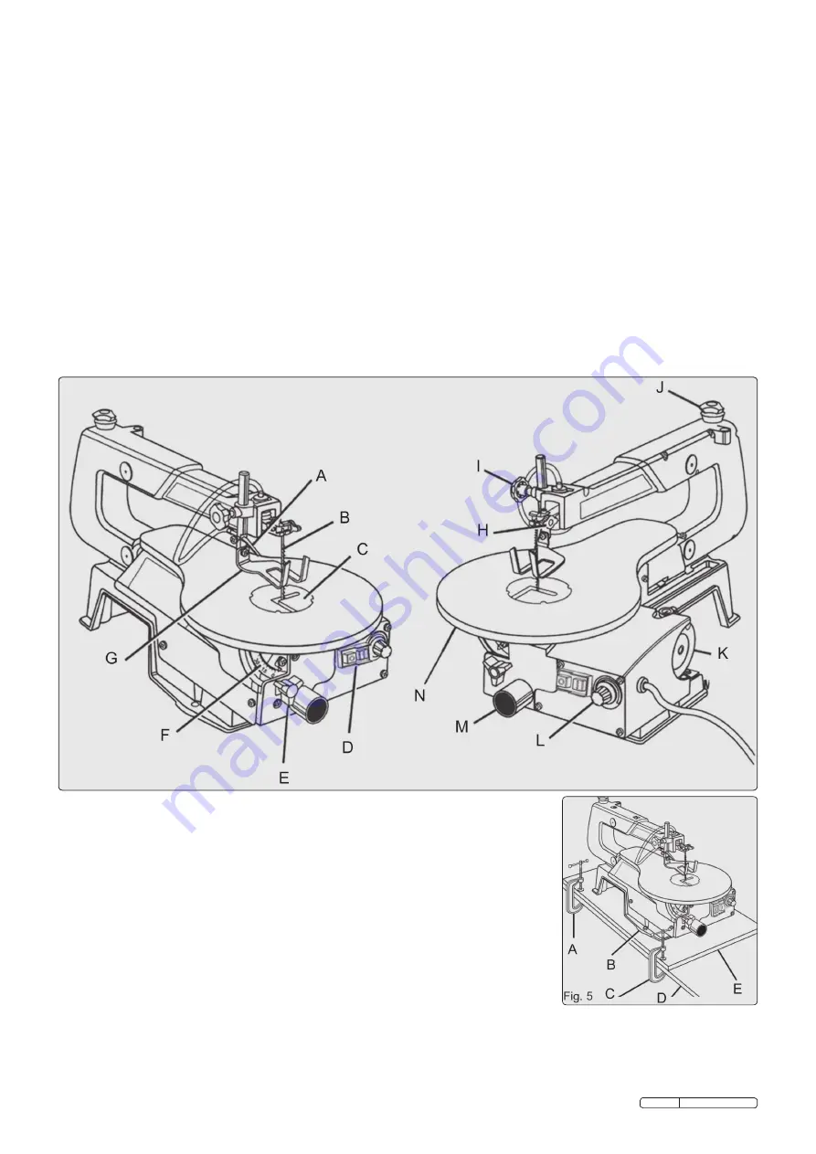
Before attempting to use your saw, familiarise yourself with all the operating features and safety requirements of your scroll saw. see figure 4.

Sawdust Blower:

 Keeps the line of cut on the workpiece clean for more accurate scroll cuts. for best results, always direct the airflow at the 

blade and the workpiece.

Saw Table with Throat Plate:

 Your scroll saw has a saw table with tilt control for maximum accuracy. the red throat plate, inserted in the saw 

table, allows for blade clearance.

Switch:

 Your scroll saw has an easy access power switch. o = off  I=on

Table Lock Knob:

 Allows you to tilt the table and lock it at the desired angle (up to 45°).

Bevel Scale:

 the bevel scale shows you the degree at which the saw table is tilted.

Drop Foot:

 this foot should always be lowered until it just rests on top of the workpiece to prevent it from lifting, yet not so much as to make 

the workpiece drag.

Blade Clamp Screws:

 Blade clamp screws are used to tighten and loosen the blade clamps when changing saw blades.

Drop Foot Lock Knob:

 this knob allows you to raise or to lower the drop foot and lock it in the required position.

Blade Tension Knob:

 to loosen or tighten blade tension, turn the blade tension knob.

Speed Selector:

 turn the knob to adjust the speed from 400 to 1,600 strokes per minute.

Sawdust Outlet:

 this feature will allow you to attach any 1¼ in. (32 mm) vacuum hose for easy sawdust collection.

Fig. 4

A.   sAWdust BloWer 

H.   BlAde clAMP screWs

B.   sAW BlAde 

I.    droP foot locK KnoB

c.   tHroAt PlAte 

J.   BlAde tensIon KnoB

d.   sWItcH 

K.   Motor

e.   tABle locK KnoB 

l.   sPeed selector

f.   BeVel scAle 

M.  sAWdust outlet

G.   droP foot 

n.   sAW tABle

4.3 

BOLTING THE SCROLL SAW ONTO A WORKBENCH. See Figure 5.


WARNING! 

to avoid serious personal injury from unexpected tool movement, securely  


mount the scroll saw onto a workbench. If the scroll saw is to be used in a specific location,  


we recommend that you secure it to a workbench in a permanent way. for this purpose,  


holes should be drilled through the supporting surface of the workbench.

4.3.1  each hole in the base of the saw should be bolted securely using machine bolts, washers,  


and nuts (not included).

4.3.2  Bolts should be long enough to accommodate the saw base, washers, nuts, and the  


thickness of the workbench.

4.3.3  Place the scroll saw on the workbench. using the saw base as a pattern, locate and mark  


the holes where the scroll saw is to be mounted.

4.3.4  drill four holes through the workbench.

4.3.5  Place the scroll saw on the workbench aligning the holes in the saw base with the holes  


drilled in the workbench.

4.3.6  Insert all four bolts (not included) and tighten securely with washers and nuts (not included).

Note:  All bolts should be inserted from the top. Fit the washers and nuts from the underside of the  


bench.


The supporting surface where the scroll saw is mounted should be examined carefully after  


mounting to insure that no movement will   occur while cutting. 


fig. 5


A. c-clAMP 


d. WorKBencH 


B. sAW BAse 


e. MountInG BoArd


c. c-clAMP

fig. 4

Original Language Version

sM1302    Issue: 2 - 12/01/10

Summary of Contents for SM1302

Page 1: ...aulty item repaired or replaced by a qualified electrician When a BS 1363 A UK 3 pin plug is damaged cut the cable just above the plug and dispose of the plug safely Fit a new plug according to the following instructions UK only a Connect the GREEN YELLOW earth wire to the earth terminal E b Connect the BROWN live wire to the live terminal L c Connect the BLUE neutral wire to the neutral terminal ...

Page 2: ... Content 4mm Hex Key Fig 1 Saw Blade Fig 2 The following tools not included are needed for adjustment and alignment Fig 3 A PHILLIPS SCREWDRIVER C COMBINATION SQUARE B SLOTTED SCREWDRIVER Bevel Cut A cutting operation made with the saw table at any angle other than 90 to the blade Compound Mitre Cut A compound mitre cut is a mitre cut with a bevel Crosscut Cut made across the grain or width of the...

Page 3: ...ig 4 A SAWDUST BLOWER H BLADE CLAMP SCREWS B SAW BLADE I DROP FOOT LOCK KNOB C THROAT PLATE J BLADE TENSION KNOB D SWITCH K MOTOR E TABLE LOCK KNOB L SPEED SELECTOR F BEVEL SCALE M SAWDUST OUTLET G DROP FOOT N SAW TABLE 4 3 bolting THE SCROLL SAW ONTO A WORKBENCH See Figure 5 WARNING To avoid serious personal injury from unexpected tool movement securely mount the scroll saw onto a workbench If th...

Page 4: ...t to direct air to the most effective point on the cutting line Make sure the drop foot is properly adjusted to secure the workpiece and direct air at the cutting surface 4 7 SQUARING THE SAW TABLE TO THE BLADE See Figure 7 WARNING To avoid accidental starting which could result in serious injury turn the saw off and unplug the saw from the power source 4 7 1 Loosen the drop foot lock knob and mov...

Page 5: ...de has the desired amount of tension 4 11 9 Replace the throat plate Note If the blade touches the drop foot on either side then the drop foot must be adjusted See section on Adjusting the Drop Foot 5 operation 5 1 OPERATION Note Before starting a cut turn the saw on and listen to the sound it makes If you notice excessive vibration or an unusual noise stop the saw immediately and unplug it Do not...

Page 6: ...til the blade has come to a complete stop 5 7 INTERIOR SCROLL CUTTING See Figure 11 5 7 1 One feature of a scroll saw is that it can be used to make scroll cuts within a workpiece without breaking or cutting through the edge or perimeter of the workpiece 5 7 2 To make interior cuts in the workpiece remove the scroll saw blade as explained in the section on Installing Blades 5 7 3 Drill a 1 4 in 6 ...

Page 7: ...ve the saw in this position overnight to let the oil soak in Note Lubricate the bearings on the other side of the saw in the same manner WARNING If the power cord is worn cut or damaged in any way have it replaced immediately by a qualified service technician Failure to do so could result in serious personal injury Fig 13 A ARM BEARINGS 6 3 CARBON BRUSHES See Figure 14 Your saw has externally acce...

Page 8: ...3B25 Blade Pitch 25tpi Pack Qty 12 Fig 15 NOTE It is our policy to continually improve products and as such we reserve the right to alter data specifications and component parts without prior notice IMPORTANT No liability is accepted for incorrect use of this product WARRANTY Guarantee is 12 months from purchase date proof of which will be required for any claim INFORMATION For a copy of our lates...

Reviews: