


WARNING! Ensure you read, understand and apply the Section 1 safety instructions.
This tool is designed for riveting metal, primarily in workshops and garages. We do not recommend any other use.
4.1.
Hydraulic oil level:
4.1.1. Disconnect the riveter from the air line.
4.1.2. Hold upside-down and remove the air cylinder cap (fig. 1.D) with the spanner provided.
4.1.3. remove the air/hydraulic piston assembly (grip exposed nut and pull).
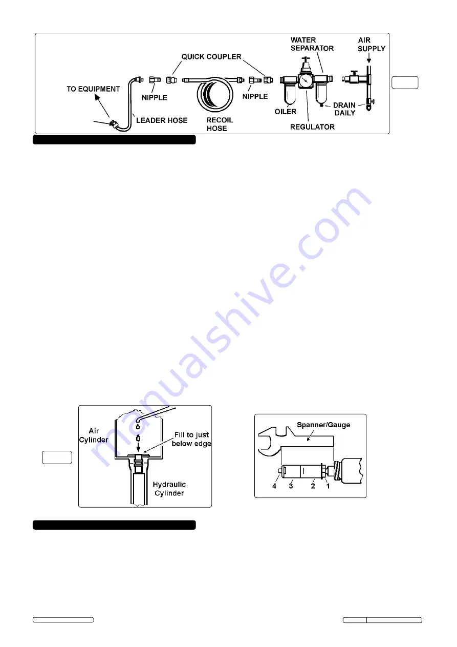
4.1.4. Add hydraulic oil to hydraulic cylinder until level is just below junction with air cylinder, see fig. 3.
4.1.5. Lightly lubricate the inner wall of the air cylinder.
4.1.6. replace the air/hydraulic piston assembly and press in as far as it will go.
4.1.7. refit and tighten the air cylinder cap.
4.2. Adjusting the stroke:
4.2.1. check that the hydraulic level is correct (see para. 4.1.).
4.2.2. remove the frame head (fig. 1.B) using the spanner provided.
4.2.3. check the jaw stroke by using the supplied spanner/gauge as in fig. 4.
4.2.4. If necessary, adjust the stroke as follows:
1) Hold the rear jaw case (fig. 4.2) with the larger spanner and loosen the lock nut (fig. 4.1) with the spanner/gauge.
2) Adjust the stroke by rotating the jaw case assembly and tighten the lock nut when adjustment is complete.
4.2.5. refit the frame head.
4.3. Changing jaws:
4.3.1. Disconnect the tool from the air line.
4.3.2. remove the frame head (fig. 1.B) using the spanner provided.
4.3.3. use both spanners to unscrew the front jaw case (fig. 4.3) from the rear jaw case (fig. 4.2).
4.3.4. remove the jaws (fig. 4.4) and clean with solvent and brush. If the teeth are blunted, replace with new jaws.
4.3.5. reverse the above procedure to reassemble.
4.4. Operation:
4.4.1.
DANGER! Always fit the safety cap (fig. 1.C) to the rear of the frame before use to prevent injury from ejected rivet stems
fit with the slot facing downwards so that stems fall to the floor.
4.4.2.
Select the nosepiece (fig. 1.A) to suit the rivet size and fit to the frame head using the spanner provided.
4.4.3.
Insert the rivet stem fully through the nosepiece and thus into the jaws.
4.4.4.
Press the rivet body through the pre-drilled hole and hold with the rivet flange flush on the workpiece.
4.4.5.
Squeeze the trigger. The rivet will be compressed and the rivet stem will be ejected into the safety cap.
4. ADJUSTMENTS & OPERATION
5. MAINTENANCE
fig. 4
fig. 3
WARNING! Ensure you disconnect the tool from the air supply system before attempting any service or maintenance.
5.1.
Maintain the tool with care. Keep it oiled for optimum performance.
5.2.
Lubricate the air tool daily with a high quality air tool oil (Sealey no. ATo/500 or ATo/1000) either via an oiler in the air supply system
or by placing a few drops into the riveter air inlet immediately before use.
5.3.
Store the tool in a safe, dry, secure environment.
5.4.
Factors that may inhibit performance:
Loss of power or erratic action may be caused by reduced compressor output, an excessive drain on the air line, moisture or restrictions
in air pipes or the use of hose connections of incorrect size. Grit or gum deposits in the tool may cut power and can be corrected by
flushing out the tool with gum solvent oil or an equivalent de-greaser. If all external conditions are in order, disconnect the tool from the
air supply, disassemble and replace any worn or damaged parts with Sealey original parts. clean all parts, reassemble and lubricate.
Alternatively, take the tool to your nearest authorised service agent.
fig. 2
Original Language Version
© Jack Sealey Limited 2013
SA31.V2 Issue: 3 (SP) - 02/09/13
DO NOT
uSE QuIcK
FIT couPLInGS AT
THIS PoInT


