4.1.
RE2311units require minimal assembly before use.
4.2.
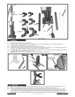
Attach the brackets item 2 to the base item 1, as illustrated in Fig.1. Be sure the brackets are fixed securely to the base as they
provide stability and will be used to secure the unit to the floor.
4.3.
Assemble the main foot pedal item 3 and secure with item 10 and item 11 (Fig.2).
4.4.
Three pairs of support yokes are supplied, with counter bored bosses for fitting to stub shafts shown in (Fig.3). Retain with the pin and "R"
clip item 14. The yokes are designed to be used as matched pairs and should not be mixed.
4.5.
The RE2311must now be fixed securely to the floor to ensure the safety of the user. Holes are to be found in the brackets which allow the
unit to be secured by way of suitable fixings into concrete.
WARNING!
Whichever method is used, ensure the unit is adequately fixed and cannot topple.
Fig.3
2
1
3
14
10,11
6
7,8,9
Contents displayed
87-129mm
106-165mm
142-202mm
12
13
Gauge
Item 1
(as
supplied)
4. ASSEMBLY
Fig.2
Fig.1
Coil compression
stub shaft (spigot)
yoke removed
Items 12 & 13
(chain anchor)
Item 2
Items 7,8,9
Items 10,11
Item 3
Removable pins
(7 height settings)
5. OPERATION
5.1.
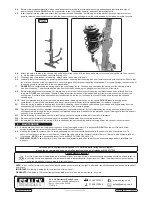
Measure the outer diameter of the spring to be compressed and select the correct set of yokes. Fit the yokes as described in section 4.4.
5.2.
Operate the release valve pedal (fig.4B) and press down on the lower strut support until the piston is full retracted.
5.3.
The upper yoke should bear down on the first full coil down from the top of the strut. The lower yoke should be pushing up on the first full
coil up from the bottom of the strut. Measure the distance between these coils and adjust the position of the upper strut support so that the
distance between the yokes is slightly larger than required. Ensure that the pins fixing the upper support are fully inserted and retained with
the spring clips provided. Use the foot pedal (fig.4A) to raise the lower yoke/strut support to finely adjust the distance between the yokes.
© Jack Sealey Limited
Original Language Version
RE2311 Issue: 1 - 10/05/16
2


