


4.2. Fitting a reel of wire.
4.2.1. Open the side compartment on the welder by pressing the black catch down to release. The interior of the side compartment is shown
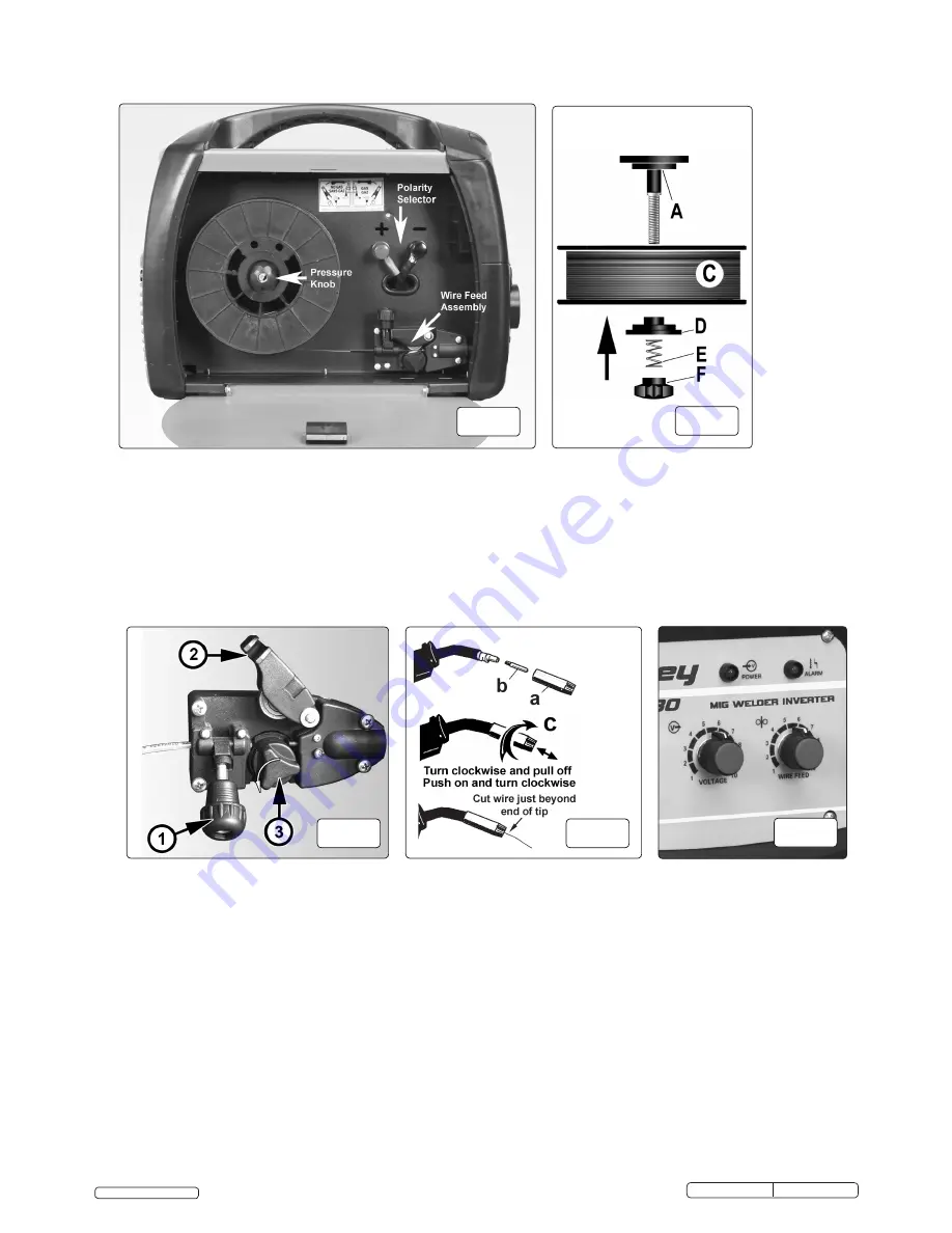
in fig. 3.
4.2.2. Rotate the pressure knob (fig.4.F) anti-clockwise and remove it from the threaded spindle together with the spring (fig.4.E) and the top disc
(fig.4.D). Small reels of wire will run on the spindle itself. The larger 5kg wire reel will run on the larger diameter flange at the base of the
reel spindle (fig.4.A). Place the wire reel (fig.4.C) onto the spindle ensuring that the wire withdraws from the spool in a forwards direction
and on the same side of the compartment as the wire feed unit. Place the plastic top disc (fig.4.D) over the end of the spindle followed by
the reel spring (fig.4.E). Thread the pressure knob (fig.4.F) onto the end of the spindle and screw it down clockwise until the spring is
partially compressed. The reel take off pressure should be set to provide a mild braking effect to prevent overrun where loose coils of wire
form on the reel. Do not overtighten this knob as too much braking will conflict with the wire tension set on the wire drive unit.
4.2.3. Turn the knob on the wire lock screw (fig.5.1) anti-clockwise and unlatch it from the pressure roller moulding. Swing the pressure roller
moulding (fig.5.2) away from the drive roller.
4.2.4 Straighten 40-50mm of spool wire (do not allow wire to uncoil), and push the wire gently through the plastic guide and through the 0.6 or
0.8mm feed roller groove and into the torch liner. Refer to section 4.5 on how to reverse the roller for either 0.6 or 0.8mm wire.
4.2.5. Move the pressure roller moulding back round onto the grooved drive wheel and swing the wire lock screw up to lock it in place.
See 4.4. regarding wire tension.
4.3. Feeding the wire through to the torch.
(fig.6)
Remove gas cup (a) and contact tip (b) from end of torch as follows:
a) Take torch in left hand with the torch tip facing to the right.
b) Grasp gas cup firmly in your right hand.
c) Turn gas cup clockwise only and pull cup out to the right.
WARNING!
do not turn gas cup anti-clockwise, as this will damage internal spring.
d) Unscrew the copper contact tip (right hand thread) to remove.
4.3.1.Check welder is switched off “0” (fig.2) and that the earth clamp is away from the torch tip. Connect the welder to the electric
power supply and set the voltage control (fig.7) to 1.
4.3.2. Set the wire speed control (fig.7) to position 5 or 6. Switch the main switch on “I”. Keep the torch cable as straight as possible
and press the torch switch. The wire will feed through the torch.
4.3.3. When wire has fed through, switch welder off, unplug from mains.
a) Take torch in left hand and screw contact tip back into place.
b) Grasp gas cup in right hand, push onto torch head and turn clockwise only.
WARNING!
do not turn gas cup anti-clockwise, as this will damage internal spring.
c) Cut the wire so that it is just protruding from the cup.
fig.3
fig.4
fig.5
fig.6
fig.7
© Jack Sealey Limited
Original Language Version
IMIG160,IMIG180 Issue: 1 - 05/01/16


