background image


Card Setup 

Sealevel Systems 

8.Ultra

 Page 

2


Card Setup 

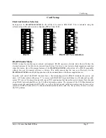
Electrical Interface Selection 

Each port on the 

8.ULTRA 

has the ability to be used in RS-422/485. This is selectable using the 

software setup utility and correctly configuring DIP-switches S1-S4.  


RS-485 Enable Modes 

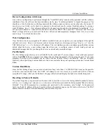
RS-485 is ideal for multi-drop or network environments. RS-485 requires a tri-state driver that will allow the 
electrical presence of the driver to be removed from the line. The driver is in a tri-state or high impedance condition 
when this occurs. One of the unique features of the 

8.ULTRA 

is the ability to be RS-485 compatible 

without the need for special software or drivers. This ability means that the user can effectively use the 

8.ULTRA 

in an RS-485 application with the standard Sealevel Software supplied drivers. 

Typically, each end of the RS-485 bus must have a line-terminating resistor (RS-422 terminates the receive end 
only). A 120-ohm resistor (silk-screen ‘T’) is across each RS-422/485 input in addition to a 1K-ohm pull-up (silk-
screen ‘PU’) and a 1K-ohm pull down (silk-screen ‘PD’) combination that biases the receiver inputs. Only the ends 
of an RS-485 network should have the 120-Ohm terminating resistor. The presence of the 120-Ohm termination 
resistor across the input data pins (RX+/RX-) as well as the pull-up and pull-down resistors may be removed or 
inserted with DIP-switches S1-S4. To add the termination/bias resistors select the ‘On’ position, to remove it select 
the ‘Off’ position. 


1
2
3
4
5
6
7

ON

OF

F

8

EN
T
PD
PU
EN
T
PD
PU

RS-232

1
2
3
4
5
6
7

ON

OF

F

8

EN
T
PD
PU
EN
T
PD
PU

RS-422/485

1
2
3
4
5
6
7

ON

OF

F

8

EN
T
PD
PU
EN
T
PD
PU

RS-422/485 No termination

Summary of Contents for SeaLINK+8.Ultra

Page 1: ...SeaLINK 8 Ultra Users Manual Part 4803 Sealevel Systems Inc Telephone 864 843 4343 155 Technology Place Fax 864 843 3067 Liberty SC 29657 USA www sealevel com...

Page 2: ...NFIGURATION 5 LINUX DEVICE DRIVER INSTALLATION 6 RAW DATA SOCKETS 6 TECHNICAL DESCRIPTION 7 CONNECTOR PIN ASSIGNMENTS 7 RS 422 485 DB 9 Male 7 RS 232 DB 9 Male 7 SPECIFICATIONS 8 ENVIRONMENTAL SPECIFI...

Page 3: ...communications for long distance device connections up to 4000ft where noise immunity and high data integrity are essential RS 485 is optimized for Multi Drop or Party line operations selecting data...

Page 4: ...8 ULTRA in an RS 485 application with the standard Sealevel Software supplied drivers Typically each end of the RS 485 bus must have a line terminating resistor RS 422 terminates the receive end only...

Page 5: ...l option is also available to remove all registry INI file entries from the system Linux If you have downloaded the source code in tar gz format type tar xzvf filename tar gz to extract the files and...
Page 6: ...allows you to configure aspects of each serial port and an administration page that lets you change the device s network and password settings Port Defaults The Port Settings page allows you to set de...

Page 7: ...uns the Select Ports Window appears Check one or more new COM ports for SeaLINK to create and click OK Note The list of COM ports will not include those already in use by Windows on this PC 4 Configur...

Page 8: ...irtualized a serial port so programs can access them just like a dev ttyS port using the termios functions see the man page for termios Note that unlike a normal serial port SeaLINK serial ports can o...

Page 9: ...X Receive Data Positive 1 Input RX Receive Data Negative 2 Input CTS Clear To Send Positive 9 Input CTS Clear To Send Negative 8 Input RS 232 DB 9 Male Signal Name Pin Mode GND Ground 5 TD Transmit Da...

Page 10: ...ture Range 0 to 70 C 32 to 158 F 50 to 105 C 58 to 221 F Humidity Range 10 to 90 R H Non Condensing 10 to 90 R H Non Condensing Manufacturing All Sealevel Systems Printed Circuit boards are built to U...

Page 11: ...all cables are connected securely 5 Verify that the Ethernet Hub Switch and any other network devices between the server and the SeaLINK device is powered up and operating 6 Ensure that the Serial Se...

Page 12: ...provides an FAQ section on its web site Please refer to this to answer many common questions This section can be found at http www sealevel com faq asp 4 Sealevel Systems maintains a web page on the...

Page 13: ...fications On a differential interface logic levels are defined by the difference in voltage between a pair of outputs or inputs In contrast a single ended interface for example RS 232 defines the logi...

Page 14: ...ion of a pre defined number of stop bits usually 1 1 5 or 2 An extra bit used for error detection is often appended before the stop bits Remain Idle or next start bit Odd Even or Unused STOP P BIT 5 t...

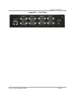
Page 15: ...Appendix E Back Panel Sealevel Systems SeaLink 8 Ultra Page 13 Appendix E Back Panel...

Page 16: ...expense EMC Directive Statement Products bearing the CE Label fulfill the requirements of the EMC directive 89 336 EEC and of the low voltage directive 73 23 EEC issued by the European Commission To o...

Page 17: ...ed from Sealevel Systems before returned merchandise will be accepted Authorization is obtained by calling Sealevel Systems and requesting a Return Merchandise Authorization RMA number The Customer ag...

Reviews: