background image


Upgrade Instructions 

With the device still plugged in, install the latest version of SeaCOM. You can 
download the latest version of SeaCOM from the product page on the Sealevel 
website. Follow the software installation steps detailed in the preceding ‘Software 
Installation’ section. 

1.


Once the SeaCOM software has been installed successfully, access Device 
Manager. 

2.


At the top of the ‘Device Manager’ window, click ‘Action’, and then click 
‘Scan for Hardware Changes’. 

3.


The ‘Found New Hardware Wizard’ window will appear. Select ‘No, not 
this time’, and then click the ‘Next’ button. 

4.


Refer to the ‘Hardware Installation’ instructions in the preceding section to 
complete the upgrade. 

5.


When the ‘Found New Hardware’ alert informs you that your hardware is 
installed and ready to use, you can proceed with verifying the installation to 
check functionality and/or locate the COM port assignments, if necessary 


© Sealevel Systems, Inc. 

- 14 - 

232-DB9 User Manual


Summary of Contents for SeaLINK+232-DB9

Page 1: ...SeaLINK 232 DB9 User Manual Item Number 2105R www sealevel com PO Box 830 Liberty SC 29657 864 843 4343...

Page 2: ...IONS 16 CONNECTOR PIN OUT 16 TECHNICAL SPECIFICATIONS 17 DIMENSIONS 17 ENVIRONMENTAL SPECIFICATIONS 17 POWER REQUIREMENTS 17 MANUFACTURING 17 APPENDIX A TROUBLESHOOTING 18 APPENDIX B HOW TO GET ASSIST...

Page 3: ...erial data activity and connection to the host Sealevel SeaCOM USB software drivers and utilities make installation and operation easy using Windows 98SE ME 2000 XP and Vista operating systems After i...

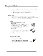
Page 4: ...4 843 4343 Cables DB9F to DB25M RS 232 Extension Cable Item CA177 The CA177 is a standard AT style RS 232 modem cable with a DB9F connector on one end and a DB25M connector on the other This cable is...

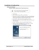
Page 5: ...Otherwise navigate to the root directory of your CD drive and double click the autorun exe application to launch the installation window 4 Select Install to locate the software and manual for your dev...

Page 6: ...eement for your records If you do not accept the terms of the agreement the installation will stop 9 When the Ready to Install the Program window appears click the Install button to install the softwa...

Page 7: ...s declaration means that SeaCOM has not been certified by Microsoft s testing labs Note All SeaCOM software and drivers have been fully tested by Sealevel Clicking Yes will not harm your system 12 If...

Page 8: ...er to the subdirectory D Software SeaCOM Other Linux replace D with your actual CD drive letter found on the Sealevel Software CD This folder contains valuable information on installing your serial ad...
Page 9: ...has been connected the Found New Hardware wizard will appear twice first for the USB hub and then for the serial port that you are installing The following instructions are applicable to the Windows...

Page 10: ...d by a message stating that the hardware has not passed Windows certification Click on Continue Anyway Note All SeaCOM software and drivers have been fully tested by Sealevel Clicking Continue anyway...

Page 11: ...Wizard appears a second time repeat steps 4 8 10 When the Found New Hardware alert informs you that your hardware is installed and ready to use you can proceed with verifying the installation to check...

Page 12: ...top or in the Start menu 2 Click Manage in the fly out menu to launch the Computer Management console window 3 In the left pane under System Tools click Device Manager 4 In right pane near the bottom...

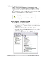
Page 13: ...tions Important Start with the hardware connected to a USB port Do not unplug it until instructed to do so Remove Hardware Using Device Manager To access Device Manager follow the steps below 1 Right...

Page 14: ...stall the SeaLINK device by clicking the OK button This will remove the hardware and all registry entries from your computer Keep the device plugged in 8 The window will refresh and the entry for the...

Page 15: ...all currently installed software on your system It may take awhile to load all of the software installed Locate the entry for SeaCOM and click to highlight 4 Click the Remove button 5 The SeaCOM Inst...

Page 16: ...e top of the Device Manager window click Action and then click Scan for Hardware Changes 3 The Found New Hardware Wizard window will appear Select No not this time and then click the Next button 4 Ref...

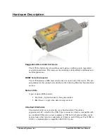
Page 17: ...Electrical Specifications section Status LEDs A pair of status LEDs indicate Tx Red Light when data is being transmitted Rx Green Light when data is being received Attached USB Cable The attached cab...

Page 18: ...Data Input 3 TD Transmit Data Output 4 DTR Data Terminal Ready Output 5 GND Ground 6 DSR Data Set Ready Input 7 RTS Request To Send Output 8 CTS Clear To Send Input 9 RI Ring Indicator Input Note The...

Page 19: ...70 C 32 to 158 F 50 to 105 C 58 to 221 F Humidity Range 10 to 90 R H Non Condensing 10 to 90 R H Non Condensing Power Requirements Supply line 5 VDC Rating 100 mA Manufacturing All Sealevel Systems Pr...

Page 20: ...ing properly in the operating system The presence of the Universal Serial Bus controllers listing in Device Manager will confirm that USB support is enabled in Windows 98 ME 2000 XP or Vista operating...

Page 21: ...the Open button See image below Click the Settings button to open the COM Properties menu Change your parameters to 9600 bits per second 8 data bits no parity 1 stop bit and no flow control as picture...

Page 22: ...x and Rx Data Rates will show the calculated data rate See image below You can continue testing this port with different configurations or proceed with testing other ports if necessary Technical Suppo...

Page 23: ...icking on the Drivers or Manuals links located under Technical Support Manuals and software can also be downloaded from the product page for your device 3 The FAQ section of our website answers many c...

Page 24: ...t Terminating Equipment Employing Serial Binary Data Interchange Both implementations are in widespread use and will be referred to as RS 232 in this document RS 232 is capable of operating at data ra...

Page 25: ...d number of stop bits usually 1 1 5 or 2 An extra bit used for error detection is often appended before the stop bits The diagram below demonstrates asynchronous communication bits This special bit is...

Page 26: ...C Directive Statement Products bearing the CE Label fulfill the requirements of the EMC directive 89 336 EEC and of the low voltage directive 73 23 EEC issued by the European Commission To obey these...

Page 27: ...ystems before returned merchandise will be accepted Authorization is obtained by calling Sealevel Systems and requesting a Return Merchandise Authorization RMA number The Customer agrees to insure the...

Reviews: