


9
© Sealevel Systems, Inc. 5402e Manual | SL9233 8/2021
Technical Description, Continued
Field
Description
IRQST
SCC interrupt status:
1 = No interrupt pending on ESCC
0 = Interrupt pending on ESCC.
DSRA
DSRA:
1 = DSRA not active
0 = DSRA active
LLA
Local Loopback:
1 = LL set
0 = LL not set
RLA
Remote Loopback:
1 = RL set
0 = RL not set
TSETSLA
TSET clock source:
1= Received TXC as source
0 = TRXCA as source
RXCOPTA
RXCOPTA:
1= Selects SCC PCLK for RTXCA
0 = Selects received RXC for
RTXCA
SYNCA_RTS
SYNCA _RTS:
1 = SYNCA connected to RTS
0 = SYNCA is high
SYNCA_CTS
SYNCA_CTS:
1 = SYNCA connected to CTS
0 = SYNCA is high
485CLK
TSET switches with
TXD:
1 = clk switches
0 = no CLK switching
ECHOA
ECHO enable:
1 = echo disabled
0 = echo enabled
AM0
–
AM3
I/O mode select. See table for valid interface options.
0 = High Impedance
SD0
–
SD15
Optional security feature. Unique value per customer or
application.
Default value = FFFF
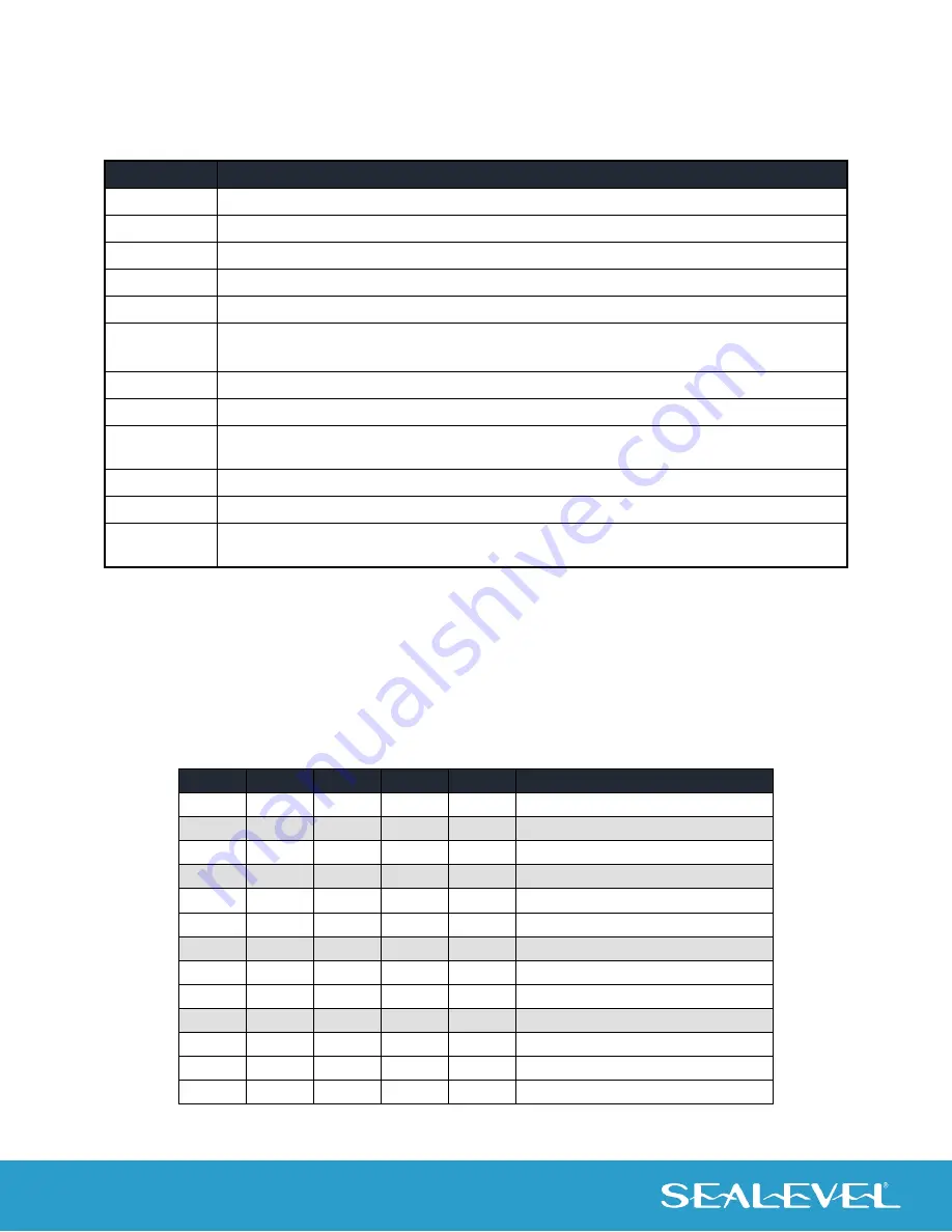
Interface Selection
The ACB-MP+4.PCIe supports a variety of electrical interfaces. Refer to the Control and Status Register
Definitions found in the Technical Description section of this manual for this bit description. There is line
termination on RXD, RXC and TXC in the following modes: RS-530, RS-530A, RS-485T and V.35. This table
is provided for users that desire to write their own driver. By default, at power-up, all signals are high
impedance.
HEX
M3
M2
M1
M0
Interface Mode
0
0
0
0
0
All signals are high impedance
1
0
0
0
1
* not supported *
2
0
0
1
0
RS-232
3
0
0
1
1
* not supported *
4
0
1
0
0
RS-485T with 120
termination
5
0
1
0
1
RS-485 without termination
6,7,8,9
0
1
1
0
* not supported *
A
1
0
1
0
single ended loopback
B
1
0
1
1
differential loopback
C
1
1
0
0
* not supported *
D
1
1
0
1
RS-530
E
1
1
1
0
V.35
F
1
1
1
1
RS-530A