background image

GLASAIR SPORTSMAN G2-2

.

Instruction  Manual.

6

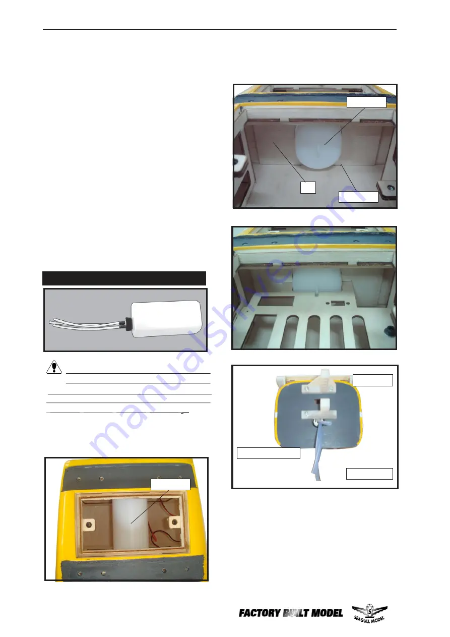
9)  Connect the lines from the tank to the engine
and  muffler.  The  vent  line  will  connect  to  the
muffler  and  the  line  from  the  clunk  to  the
carburetor.

Fuel tank.

Vent tube.

Fuel pick up tube.

Fuel fill tube.

3) Carefully bend the second nylon tube

up at a 45º angle.  This tube is the vent tube.

4) Test fit the stopper assembly into the

tank.  It may be necessary to remove some of
the flashing around the tank opening using a
modeling knife.  If flashing is present, make
sure none falls into the tank.

5) With  the  stopper  assembly  in  place,

the weighted pick-up should rest  away from
the rear of the tank and move freely inside the
tank.  The top of the vent tube should rest just
below the top of the tank.  It should not touch
the top of the tank.

6) When satisfied with the alignment of

the stopper assembly tighten the 3 x 20mm
machine  screw  until  the  rubber  stopper  ex-
pands  and  seals  the  tank  opening.    Do  not
overtighten the assembly as this could cause
the tank to split.

You should mark which tube is the vent

and which is the fuel pickup when you attach
fuel tubing to the tubes in the stopper. Once
the tank is installed inside the fuselage, it may
be difficult to determine which is which.

FUEL TANK INSTALLATION.


7)  Slide the fuel tank into the fuselage. Guide

the  lines  from  the  tank  through  the  hole  in  the
firewall.

Fuel tank.


8)    Use  plywood  template  to  hold  in  place

the  fuel  tank  with  C/A  glue  to  secure  the  fuel
tank  inside  the  fuselage.

A.

C/A glue.

Summary of Contents for GLASAIR Sportsman GS-2

Page 1: ...ice MS 158 ASSEMBLY MANUAL Specifications Wingspan 70 9in 180cm Wingarea 644 8sq in 41 6sqdm Weight 9 5 11 5lbs 4 3 5 2kg Length 49 2n 125 0cm Engine 0 75 0 91cu in 2 stroke 0 91 1 10cu in 4 stroke Radio 6channelswith8servos Electric conversion optional ...

Page 2: ...manual is designed to help you build a great flying aeroplane Please read this manual thoroughly beforestartingassembly ofyour GLASAIRSPORTSMAN G2 2 Use the parts listing below to identify all parts WARNING Please be aware that this aeroplane is not a toy and if assembled or used incorrectly it is capable of causing injury to people or property WHEN YOU FLY THIS AEROPLANE YOU ASSUME ALL RISK RESPO...

Page 3: ...r 90 square or builder s triangle Wire cutters Masking tape T pins Thread lock Paper towels 1 Fuselage 2 Left wing panel 3 Right wing panel 4 LED lights 5 Tail set 6 Wheel pants 2 7 Seat 2 8 landing gear 9 Tail wheel 10 Struts 11 Cowling 12 Fuel tank 13 canopy 14 Wheels and spinner 15 Aluminum wing tube 16 Pilots 17 Hardware bag included 18 Ep conversion pack 19 Engine mount KIT CONTENTS TS INSTAL...

Page 4: ...NTROL HORN Epoxy Epoxy Elevatorcontrol horn INSTALL RUDDER CONTROL HORN Epoxy Repeat steps to install the rudder control horn as same as steps done for ailerons Rudder control horn Epoxy Fiberglass control horn Fiberglass control horn Epoxy Epoxy Flap control horn ...

Page 5: ...threadlock on the screws to help prevent them from vibrating loose 4x30mm INSTALLING THE STOPPER ASSEMBLY 2 Using a modeling knife cut one length of silicon fuel line Connect one end of the line to the weighted fuel pick up and the other end to the nylon pick up tube 1 Using a modeling knife carefully cut off the rear portion of one of the 3 nylon tubes leaving 1 2 protruding from the rear of the ...

Page 6: ...ove freely inside the tank The top of the vent tube should rest just below the top of the tank It should not touch the top of the tank 6 When satisfied with the alignment of the stopper assembly tighten the 3 x 20mm machine screw until the rubber stopper ex pands and seals the tank opening Do not overtighten the assembly as this could cause the tank to split You should mark which tube is the vent ...

Page 7: ...your radio system Because the size of servos differ you may need to adjust the size of the precut open ing in the mount The notch in the sides of the mount allow the servo lead to pass through Rudder servo THROTTLE SERVO ARM INSTALLATION Install adjustable servo connector in the servo arm as same as picture below Adjustable Servo connector Servo arm Loctite secure 1 PCS Throttle servo arm Elevator...

Page 8: ...ng the axles and wear protective goggles Drill a hole wheel collar wheel Axle Washer M3 wheel Pant wheel M3 M3 wheel collar nut Axle Washer M3 4 Slide the collar to the axle and setscrew the collars to secure the collar to the axle and then slider the wheel on the axle with a drop of oil on the axle so the wheel will spin freely when installed Prepare a second collar and tighten the setscrew using...

Page 9: ...anding gear Make sure to use threadlock on the nut so it won t vibrate loose in flight as shown C A glue Landing Gear wheel Pant Locker glue 7 Tighten the setcrews using a hex wrench to secure the collars on the axle over the flat spot to retain the wheel as shown Repeat steps as above to attach remain ing wheel pants to the landing gear 4x20 mm 145mm MOUNTING THE ENGINE 1 Position the engine with...

Page 10: ...o the tube Position the engine between the mounts Use four M4x30mm machine screws to secure the engine to the mount as shown Machine screw M4x30mm Pushrod wire 9 Move the throttle stick to the closed position and move the carburetor to closed Use a 2 5mm hex wrench to tighten the screw that secures the throttle pushrod wire Make sure to use threadlock on the screw so it does not vibrate loose 3 Us...

Page 11: ...d cut 1 Slide the fiberglass cowl over the engine and line up the back edge of the cowl with the marks you made on the fuselage then trim and cut as shown Trim and cut Trim and cut 2 Install LED lights at the top Cowling Electric wire 5mm Drill a hole 5mm ...

Page 12: ...ne The front of the cowl should be positioned so the crankshaft is in nearly the middle of the cowl opening Use the spinner backplate as a guide Hold the cowl firmly in place using pieces of masking tape Because of the size of the cowl it may be nec essary to use a needle valve extension for the high speed needle valve Make this out of suf ficient length 1 5mm wire and install it into the end of t...

Page 13: ...agullmodels com 4mm 3 Attach the motor to the front of the electric motor box using four 4mm blind nut four M3x15mm hex head bolts to secure the motor Please see picture shown M4x20mm 4mm M3x15mm 145mm Blind nut ...

Page 14: ...ith it Speed control Tie wraps Battery 5 Attach the speed control to the side of the motor box using two sided tape and tie wraps Connect the appropriate leads from the speed control to the motor Make sure the leads will not interfere with the operation of the motor Balsa stick Electric motor 4 Locate the plywood battery tray to the fuselage Tighten the screws using machine screws M3x15mm to secur...

Page 15: ... to adjust the size of the precut open ing in the mount The notch in the sides of the mount allow the servo lead to pass through 3 Use drill bit in a pin vise to drill the mouting holes in the blocks 4 Apply 2 3 drops of thin C A to each of the mounting holes Allow the C A to cure without using accelerator 5 Use dental floss to secure the connection so they cannot become unplugged 6 Secure the ser...

Page 16: ...g has been provided in the wing to pull the aileron lead through to the wing root Remove the string from the wing at the servo location and use the tape to attach it to the servo extension lead Pull the lead through the wing and remove the string C A glue ...

Page 17: ...nstall it with four wood screws AILERON PUSHROD HORN INSTALLATION M2 lock nut M2 clevis 40mm 70mm Wing Aileron M2 lock nut INSTALLING THE FLAP SERVO Repeat the procedure for the aileron servo Wing Flag M2 lock nut M2x10mm Aileron Wing Aileron Repeat the procedure for the other aileron servo Wing ...

Page 18: ... remove any excess epoxy using a paper towel and rubbing alcohol Pen Trim and cut 5 Remove the stabilizer Using the lines you just drew as a guide carefully remove the covering from between them using a model ing knife 4 With the stabilizer held firmly in place use a pen and draw lines onto the stabilizer where it and the fuselage sides meet Do this on both the right and left sides and top and bot...

Page 19: ... check to ensure that the vertical stabilizer is aligned 90º to the hori zontal stabilizer Epoxy Epoxy 4 When you are sure that everything is aligned correctly mix up a generous amount of Flash 30 Minute Epoxy Apply a thin layer to the mounting slot and to bottom of the vertical sta bilizer mounting area Apply epoxy to the bot tom and top edges of the filler block and to the lower hinge also Set t...

Page 20: ...e elevator control horn on the both side of elevator 4 Elevator and rudder pushrods assembly as pictures below 3 Thread one clevis and M2 lock nut on to each elevator control rod Thread the horns on until they are flush with the ends of the con trol rods Control horn M2 lock nut Metal clevis Rudder pushrod Rudder pushrod RUDDER PUSHROD HORN INSTALLATION Rudder control horn M2 lock nut M2 clevis 66...

Page 21: ...locations for the tailwheel support 2 Temporarily mount the tailwheel assembly to the bottom of rudder Do not glue at this time Slide the nylon tailwheel support brackets to be evenly spaced along the tailwheel wire Epoxy 4 Drill through the bottom of the rudder with the 2mm drill 5 Using a toothpick insert a small amount of the epoxy in the hole in the bottom of the rudder Insert the vertical tai...

Page 22: ...GLASAIR SPORTSMAN G2 2 Instruction Manual 22 INSTALLATION THE WING STRUTS 2 1 Tail Wheel pushrod Epoxy Wing set 1 2 TAILWHEEL PUSHROD HORN INSTALLATION ...

Page 23: ...factory They are available at Seagull distributors 3 Position the pilot figure on the canopy floor as show Locate the oval shaped on the canopy floor and remove the covering Use epoxy to glue this into the base of the pilot figure and glue the cockpit panel in place with C A glue please see pictures as shown If you are going to install a pilot figure please use a sanding bar to sand the base of th...

Page 24: ...er to protect them from vibration APPLY THE DECALS 1 If all the decals are precut and ready to stick Please be certain the model is clean and free from oily fingerprints and dust Position decal on the model where desired using the photos on the box and aid in their location 2 If all the decals are not precut please use scissors or a sharp hobby knife to cut the decals from the sheet Please be cert...

Page 25: ...25 www seagullmodels com Insert two wing panels as pictures below INSTALLATION WING FUSELSGE STRUTS Wing Wing M3x10mm M3x25mm 2mm M3x10mm Screw ...

Page 26: ...GLASAIR SPORTSMAN G2 2 Instruction Manual 26 OPTIONAL FLOAT SET FOR GLASAIR SPORTMAN 1 Install Struts onto floats Screw 1 5 4 3 2 5 M3x10mm 2 5 Screw M4x20mm ...

Page 27: ...27 www seagullmodels com Screw M4x10mm 2 Install Water Rudder 1 3 4 2 5 7 6 1 2 1 2 Screw M4x10mm ...

Page 28: ...GLASAIR SPORTSMAN G2 2 Instruction Manual 28 Screw Screw Screw M3x25mm 1 6 Add Rubber Band ...

Page 29: ...29 www seagullmodels com 3 Float attachment to fuselage Screw Screw 4 Install water rudder control bellcrank to fuselage 1 Screw 2 M3x15mm M3x15mm M4x20mm M4x20mm ...

Page 30: ...G ROOT 4 Do not turn plane upside down Only low wing models should be turned upsidedown for balancing High Wing models must be balanced upright 2 Mount the wing to the fuselage Using a couple of pieces of masking tape place them on the top side of the wing 60 mm back from the leading edge of the wing at the wing root 1 2 1 2 1 2 5 Install water rudder control cables 3 Turn the airplane upside down...

Page 31: ... the proper balance point Accurately mark the balance point on the botttom of the wing on both sides of the fuselage The balance point is located 60 mm back from the leading edge of the wing at the wing root This is the balance point at which your model should balance for your first flights Later you may wish to experiment by shifting the balance up to 10mm forward or back to change the flying cha...

Page 32: ...n the low rate setting for your first few flights 2 Check every bolt and every glue joint in the GLASAIR SPORTSMAN G2 2 to ensure that everything is tight and well bonded 6 Check to ensure the control surfaces are moving the proper amount for both low and high rate settings 1 Completely charge your transmitter and receiver batteries before your first day of flying 8 Properly balance the propeller ...

Reviews: