Seagull Models CAP 232 Assembly Manual Download Page 3

www.seagullmodels.com

3


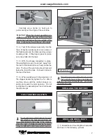
1) Carefully remove the aileron from one

of the wing panels. Note the position of the
hinges.


2) Remove each hinge from the wing panel

and aileron and place a T-pin in the center of
each hinge. Slide each hinge into the wing
panel until the T-pin is snug against the wing
panel. This will help ensure an equal amount
of hinge is on either side of the hinge line when
the aileron is mounted to the aileron.


3) Slide the wing panel on the aileron until

there is only a slight gap. The hinge is now
centered on the wing panel and aileron.
Remove the T-pins and snug the aileron
against the wing panel. A gap of 1/64” or less
should be maintained between the wing panel
and aileron.

The control surfaces, including the
ailerons, elevators, and rudder, are
prehinged with hinges installed, but the
hinges are not glued in place. It is
imperative that you properly adhere the
hinges in place per the steps that follow
using a high-quality thin C/A glue.

Note:


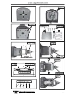
4)Deflect the aileron and completely

saturate each hinge with thin C/A glue. The
ailerons front surface should lightly contact the
wing during this procedure. Ideally, when the

hinges are glued in place, a 1/64” gap or less
will be maintained throughout the lengh of the
aileron to the wing panel hinge line.

Note:

The hinge is constructed of a special
material that allows the C/A to wick or
penetrate and distribute throughout the
hinge, securely bonding it to the wood
structure of the wing panel and aileron.

              To avoid scratching your new aero-
plane we suggest that you cover your work-
bench with an old towel. Keep a couple of jars
or bowls handy to hold the small parts after you
open the bags.

Please trial fit all parts. Make sure you have the
correct parts and that they fit and are aligned
properly before gluing! This will ensure proper
assembly as the   

CAP 232


is made from

natural materials and minor adjustments may
have to be made.        The paint and plastic parts
used in this kit are fuel proof. However, they are
not tolerant of many harsh chemicals includ-
ing the following: paint thinner, cyano-acrylate
glue accelerator, cyanoacrylate glue de-bonder
and acetone. Do not let these chemicals come
in contact with the colours on the covering and
the plastic parts.

NOTE:

HINGING THE AILERONS.


5) Turn the wing panel over and deflect the

aileron in the opposite direction from the
opposite side. Apply thin C/A glue to each
hinge, making sure that the C/A penetrates into
both the aileron and wing panel.


6) Using C/A remover/debonder and a

paper towel, remove any excess C/A glue that
may have accumulated on the wing or in the
aileron hinge area.

C/A glue.

Hinge.

Hinge.

T- pin.

Hinge.

T- pin.

Summary of Contents for CAP 232

Page 1: ...165cm Wing area 782 8 sq in 50 5 sq dm Approximate flying weight 9 7lbs 4 4kg Length 58 8 in 149 4cm Recommended engine size 75 91 cu in 2 stroke 1 00 1 14 cu in 4 stroke ELECTRIC CONVERSION OPTIONAL Radio System required 4 channels with 6 servos Flying skill level Intermediate advanced Graphics and specifications may change without notice ASSEMBLY MANUAL MS SEA 91 CAP 232 ...

Page 2: ...ISK RESPONSIBILITY If you are inexperienced with basic R C flight we strongly recommend you contact your R C supplier and join your local R C Model Flying Club R C Model Flying Clubs offer a variety of training procedures designed to help the new pilot on his way to successful R C flight They will also be able to advise on any insurance and safety regulations that may apply ADDITIONAL ITEMS REQUIR...

Page 3: ... throughout the lengh of the aileron to the wing panel hinge line Note The hinge is constructed of a special material that allows the C A to wick or penetrate and distribute throughout the hinge securely bonding it to the wood structure of the wing panel and aileron To avoid scratching your new aero plane we suggest that you cover your work bench with an old towel Keep a couple of jars orbowlshand...

Page 4: ...is process with the other wing panel securely hinging the aileron in place HINGING THE RUDDER Glue the elevator hinges in place using the same techniques used to hinge the ailerons Glue the rudder hinges in place using the same techniques used to hinge the ailerons Work the aileron up and down several times to work in the hinges and check for proper movement Note Aileron control horn installation ...

Page 5: ... aileron control horns 2 sets 3x35mm Rudder control horn Using the same techniques used aileron control horn See picture below 2 sets 3x45mm Rudder control horn 16mm Epoxy RUDDER CONTROL HORN Horizontal Stabilizer Elevator control horn CONTROL HORN M3 SCREW ALUMINUM WASHER ALUMINUM WASHER M3 LOCK NUT EPOXY FUSELAGE Rudder 18mm EPOXY Fuselage Rudder Horizontal Stabilizer Elevator ...

Page 6: ... up at a 45º angle This tube is the vent tube 1 Using a modeling knife carefully cut off the rear portion of one of the 3 nylon tubes leaving 1 2 protruding from the rear of the stopper This will be the fuel pick up tube INSTALLING THE STOPPER ASSEMBLY Thread locker glue See pictures below Make yourself the template of your engine on paper ENGINE MOUNT INSTALLATION Mark and drill 4 holes for engin...

Page 7: ... use a lighter or heat gun to permenently set the angle of the vent tube 6 When satisfied with the alignment of the stopper assembly tighten the 3 x 20mm machine screw until the rubber stopper ex pands and seals the tank opening Do not overtighten the assembly as this could cause the tank to split FUEL TANK INSTALLATION You should mark which tube is the vent and which is the fuel pickup when you a...

Page 8: ...the main landing gear to the fuselage INSTALLING THE MAIN LANDING GEAR 3 A drop of C A glue on the wheel collar screws will help keep them from coming lose during operation Repeat the process for the other wheel wheel collar wheel Lite Plywood block Axle Washer M3 wheel Pant wheel M3 wheel collar Lite Plywood block nut Axle Washer Landing Gear 4x20mm 14mm 7mm wheel Pant Locker glue Locker glue C A...

Page 9: ...rews Double check that all the screws are tight before proceeding 4 Remove the engine Using an drill bit drill the mounting holes through the engine mount at the four locations marked 2 Place your engine onto the engine mount Adjust the engine is centered of the edges of the engine case 3 When you are satisfied with the align ment mark the locations of the engine mounting 140mm 4 2 mm diameter Mac...

Page 10: ...uf ficient length 1 5mm wire and install it into the end of the needle valve Secure the wire in place by tightening the set screw in the side of the needle valve 2 While keeping the back edge of the cowl flush with the marks align the front of the cowl with the crankshaft of the engine The front of the cowl should be positioned so the crankshaft is in nearly the middle of the cowl opening Use the ...

Page 11: ...llmodels com 11 M5 x 100mm 140mm C A glue C A glue Battery A Battery hatch M3x10mm M3x15mm 3 2 1 2 1 1 Aluminum spacers Aluminum tube B A 4 sets Aluminum tube B B B B Electric motor Electric motor Electric motor ...

Page 12: ...ion Manual 12 Pen SPINNER INSTALLATION Machine Screw M3x10mm needlevalve Trim and cut Battery hatch Battery hatch INSTALLING THE SWITCH Install the switch into the precut hole in the side of fuselage Switch 3 3 M3x10mm ...

Page 13: ...ator servo Rudder servo Throttle servo arm Elevator servo Elevator servo Rudder servo INSTALLING THE AILERON SERVOS Servos Small weight Thread Installing the aileron servo in place using the same techniques used to flap servo String Small weight Electric wire Aileron Servo Attach the string to the servo lead and carefully thread it though the wing String Small Weight Wing String Small Weight Wing ...

Page 14: ...nstruction Manual 14 Repeat the procedure for the other wing Wing Aileron M3 lock nut WING ASSEMBLY AILERON PUSHROD HORN INSTALLATION Wing Aileron M3 lock nut M3 clevis 85mm 115mm Aileron Wing Wing Aileron Epoxy ...

Page 15: ...STALLING THE HORIZONTAL STABILIZER Center line Hinge slot Remove covering Pen Epoxy When cutting through the covering to remove it cut with only enough pressure to only cut through the covering itself Cut ting into the balsa structure may weaken it ...

Page 16: ...CAP 232 Instruction Manual 16 90º Vertical Stabilizer Horizontal Stabilizer Fill epoxy Epoxy C A glue Hinge Masking tape Remove covering INSTALLING THE VERTICAL STABILIZER Masking tape Hinge ...

Page 17: ...SHROD HORN INSTALLATION Elevator control horn Rudder control horn Rudder pushrod Control horn Elevator Pushrod Metal clevis Elevator pushrod M2 lock nut M2 clevis M2 Lock nut Attach to servo arm in fuselage Attach to elevator rudder control horn ...

Page 18: ...CAP 232 Instruction Manual 18 Elevator Elevator Rudder Throttle M3x25mm MOUNTING THE TAIL WHEEL See picture below M3x30mm M3x25 mm M3x30 mm 22mm Rudder M3x30 mm Elevator Rudder Throttle ...

Page 19: ...d Bolt the wing to fuselage See pictures below ATTACHMENT WING FUSELAGE Wing bolt Wing bolt 1 It is critical that your airplane be bal anced correctly Improper balance will cause your plane to lose control and crash The cen ter of gravity is locate 65mm back from the leading edge of the wing measured at wing tip BALANCING 60mm ...

Page 20: ... Check the control surfaces All should move in the correct direction and not bind in any way 2 If the nose of the plane falls the plane is nose heavy To correct this first move the battery pack further back in the fuselage If this is not possible or does not correct it stick small amounts of lead weight on the fuselage sides under the horizontal stabilizer If the tail of the plane falls the plane ...

Page 21: ... Properly balance the propeller An out of balance propeller will cause excessive vi bration which could lead to engine and or air frame failure We wish you many safe and enjoyable flights with your CAP 232 7 Check the receiver antenna It should be fully extended and not coiled up inside the fuselage AEROBATIC FLYING INITIAL FLYING ...

Reviews: