
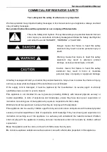
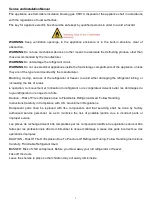


Service and Installation Manual
4
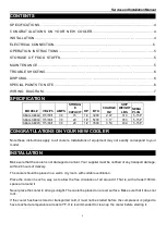
CONTENTS
SPECIFICATIONSEEEEEEEEEEEEEEEEEEEE.EEEEEEEEE.EEE4
CONGRATULATIONS ON YOUR NEW COOLEREEEEEEEEEEEEEE.EEE4
INSTALLATIONEEEEEEEEEEEEEEEEEEEEEEEEEEEE.EEEE..E...4
ELECTRICAL CONNECTIONEEEEEEEEEEEEEEEEEEEEEEEEEEE.....E.5
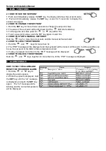
OPERATION INSTRUCTIONSEEEEEEEEEEEEEEEEEEEEEE..EEEEE5
STORAGE OF FOOD STUFFS..EEEEEEEEEEEEEEEEEEEEEEEEEEE5
MA INT ENA NCE E EEEE EEE EE EEEE EEE EE EEEE EE.E EE EEE.5
TROUBLE SHOOTINGEEEEEEEEEEEEEEEEEEEEEEEEEEEEEEEE.6
DISPOSALEEEEEEEEEEEEEEEEEEEEEEEEEEEEEEEEEEEEE6
SPECIAL PIONTS TO NOTEEEEEEEEEEEEEEEEEEEEEEEEEEEEEEE6
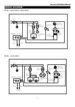
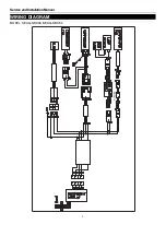
W IRING DIAGRAMEEEEEEEEEEEEEEEEEEEEEEEEEEEEEEE7
SPECIFICATION
MODEL#
V/Hz/Ph AMPS
STORAG
E
CAPACIT
HP
BTU
CHARGE
OZ
SHIP
WEIGHT
LBS
NEMA
PLUG
SEAG-S
BC
49
115/60/1
3.0
15
1/2
3200
2.47
310
5-15P
SEAG-S
BC6
4
115/60/1
3.0
20
1/2
5400
3.17
353
5-15P
SEAG-S
BC95
115/60/1
3.3
26
1/2
7600
3.53
439
5-15P
CONGRATULATIONS ON YOUR NEW COOLER
Note these instructions apply to all coolers. Installations of equipment may not exactly correspond to your
model.
INSTALLATION
Make sure that the cooler is not damaged on arrival. Your supplier must be notified of any transport damage,
within 24 hours of delivery.
The cooler should be placed in a warm, dry room, with suitable ventilation.
Place the cooler in such a way, as to allow the free circulation of air around it. That is, with at least 100mm
space all around it.
Never place the cooler in strong sunlight. The cooler be placed on a level surface. Make sure that it does not
rock.
If the cooler has been stored or transported cold, it must not be started before the compressor is judged to
have reached a temperature at least 41°F. It is recommended to clean up the cooler before starting it.