SC4x0 Technical manual
Page 18 of 34
SeaCom
Rev
2.00
8. Electrical layout
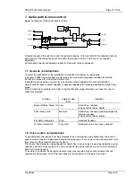
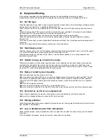
Below a schematic of the electrical layout is shown.
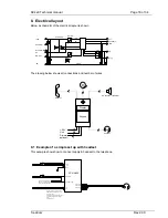
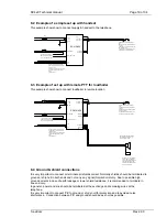
The drawing below shows all connections and number of wires.
8.1 Example of a simple set up with headset
This example shows how to connect supply & headset to the telephone.
+24V
Frame
PE
Dimmer
0V
Hook SW 0V
Hook SW
Power Amp.
DC/DC
0V
+5V
Line
Tip
Ring
PTT
Speakers
Mic.
Display
Keypad
Line
+24V
Dimmer
(optional)
2
2
2
2
6
6
2
Headset
Handset
Ext. speaker / Loudhailer
PE
Headset SP
Headset PTT
Headset Mic
SC410/420
+24V
0V
Relay COM
Relay NO (or NC)
PE
T1A
T2A
PE
NOTE: If shield is connected at
APBX do NOT connect to PE at
telephone end
Always only connect one end due
to possibly high ground current
when
used off shore
To bell or alarm relay coil
NOTE: If connected to DC
coil –use protection diode.
Line

