background image


DOCS-004 Manual, LBV300-6 and LBV600-6 Rev C – 12APR10 Page 4 of 8 


Section 3: Care and Troubleshooting of the Fiber Optic Cable. 


While SeaBotix Inc. has made every attempt to provide strength around 
the fiber optic line, care MUST be taken to ensure a long lasting 
dependable connection. 

 
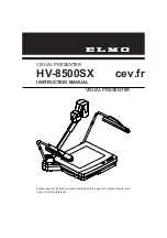
WHEN CONNECTING THE TETHER TO THE LBV, ATTACH THE SHACKLE 
FIRST, THEN CONNECT THE FIBER OPTIC LINE, FOLLOWED BY THE 
POWER CABLE.   


WHEN DISCONNECTING THE TETHER FROM THE LBV, DISCONNECT 
THE POWER CONNECTOR FIRST, FOLLOWED BY THE FIBER OPTIC 
CONNECTOR, AND THEN THE SHACKLE.  REPLACE ALL PROTECTIVE 

COVERS AND CAPS. 


3.0.1 Never place bends of less than 150mm (6”) dia. on the fiber optic lines or the 
tether. 
 
3.0.2 When operation of the LBV is complete, rinse both the fiber and power 
connectors with fresh water. 
 
3.0.3 Always dry the end of the fiber connector before installing the protective boot cap. 
 
3.0.4 Always ensure that the fiber bulkhead connector on the LBV is dry prior to 
connecting the tethers fiber connector.  
 
3.0.5 Do not use sharp objects to clean out the fiber connector.  It is ok to just blow the 
water out with low pressure (less than 1 bar,) air.  Canned computer dusting air is a 
suitable source for the low pressure air. 
 
3.0.6 Do not pull the LBV by the fiber optic line. 
 
3.0.7 When placing the reel into the shipping case, make sure that the fiber line is 
secure so it, and will not be damaged when the transit case lid is closed. 


Fiber Optic Line 

Power 
Connector 

Summary of Contents for DOCS-004

Page 1: ...9437 5400 2009 by SeaBotix Inc All Rights Reserved ADDENDUM USER MANUAL LBV300S 6 LBV300XL LBV600XL DOCS 004 Rev C The information photographs illustrations and descriptions contained in this manual are the property of SeaBotix Inc Unauthorized duplication and distribution is strictly forbidden Additionally SeaBotix Inc reserves the right to alter any and all information contained in this manual ...

Page 2: ...r 09 Contents Section 1 The LBV 1 Section 2 Bumper Frame and Float Removal 3 Section 3 Care and Troubleshooting of the Fiber Optic Cable 4 3 1 Data Communications error and or loss of video 5 3 2 No Link 7 Section 4 URS350 or URS750 REEL 8 ...

Page 3: ...on 1 The LBV The LBV should always be handled by the bumper frame only Utilize the cutouts as shown below to handle the LBV Do not utilize the thruster guards the thrusters or any other attached devices as they are not designed to handle the weight of the LBV in the air ALWAYS LIFT THE LBV BY THE HANDLE HOLES PROVIDED 1 1 The LBV300XL and LBV600XL have been equipped with a 1200 watt Vehicle Power ...

Page 4: ...that of the LBV150 The communications and video transfer takes place via a fiber optic line inside the tether 1 3 To trim the weight on the LBV use the lead strip mounting locations as shown above blue arrows 1 4 Always trim your LBV for the water in which you will be flying it Proper trim facilitates LBV control and extends thruster life ...

Page 5: ...BV Lay each bumper frame to the side 2 5 Use the service manual instructions for removing a body float to remove the LBV float 2 6 Remove the cables from the aux 1 and aux 2 connections on the backplane This procedure now frees the bumper frames from the LBV Assembly and disassembly instructions are identical to the instructions on the SeaBotix Inc web site for assembly and disassembly of the LBV1...

Page 6: ...an 150mm 6 dia on the fiber optic lines or the tether 3 0 2 When operation of the LBV is complete rinse both the fiber and power connectors with fresh water 3 0 3 Always dry the end of the fiber connector before installing the protective boot cap 3 0 4 Always ensure that the fiber bulkhead connector on the LBV is dry prior to connecting the tethers fiber connector 3 0 5 Do not use sharp objects to...

Page 7: ...ey is not aligned correctly 2 Water in the bulkhead connector 3 Foreign object or debris in the bulkhead 3 1 Data Communications error and or loss of video The image on the next page is the Local Fiber Optic Board PCA039 mounted in the Pull Out Hub of the Universal Reel System By component layout it is identical to the board mounted in the camera chassis of the LBV The part number for the LBV boar...

Page 8: ...ta Transmission Blinking RED indicates NORMAL state Data Transmitting Channel 2 RS 485 TX OUT GREEN Solid GREEN indicates HIGH state No Data Transmission LED OFF indicates LOW state but No Data Transmission Blinking GREEN indicates NORMAL state Data Transmitting 6 Channel 3 RS 232 RX IN RED LBV Control Solid RED indicates HIGH state No Data Transmission Check RS 232 GND Pin 1 connection LED OFF in...

Page 9: ...mission the fiber optic cable inside the tether is damaged At this point you will need to get access to a fiber optic TDR Time Delay Reflectometer to determine at what point in the tether the damage has occurred SeaBotix Inc does offer a Fiber Optic Re termination Kit to allow the user to complete this repair in the field Please contact service seabotix com to assist in identifying the proper kit ...

Page 10: ...t back from the reel Use this same procedure to remove the handle from the handle holder 4 3 Avoid lifting the reel by the chrome bars ALWAYS USE AT LEAST TWO PEOPLE TO LIFT THE REEL ALWAYS SECURE THE REEL TO THE DECK OR THE DOCK UNDER HIGH LOAD CONDITIONS MONITOR THE TEMPERATURE OF THE TETHER ON THE REEL IF IT STARTS GETTING WARM POUR COOL WATER OVER THE TETHER EVERY FEW MINUTES If you have any q...

Reviews: