NOTES
The electrical installation and the operation logics must comply with current regulations. Keep the power cables (motors, power supply)
separated from the control cables (push-buttons, photo-eyes, radio, etc.). Separate conduits should be used to prevent noise issues.
Note:
Use “cable clips” and/or “duct/box pipes” fitting close to the control panel box so to protect the interconnection cables against pulling
efforts.
INTENDED USE
VERG system has been designed exclusively for the automation of barriers.
SPARE PARTS
The spare parts orders must be sent to:
SEA S.p.A. Zona Ind.le, 64020 S.ATTO Teramo Italy
SAFETY AND RESPECT FOR THE ENVIRONMENT
We recommend not to spoil the environment with product and circuit packing material.
STORAGE
STORAGE TEMPERATURE
T
min
-30°C
T
max
+60°C
Humidity
min
5% without condensation
Humidity
max
90% without condensation
The product must be handled using suitable means.
LONG-TERM STOP AND MAINTENANCE
The disassembly and/or stop and /or maintenance of the VERG automation system must be carried out by skilled and expert technicians.
GUARANTEE LIMITS
For the guarantee see the sales conditions on the official SEA price list.
NOTE: THE MANUFACTURER SHALL NOT SHOULDER ANY RESPONSIBILITIES IN CASE OF DAMAGE CAUSED BY
INAPPROPRIATE, WRONG OR CARELESS USE.
SEA reserves the right to make all the necessary changes and modifications of the products and / or manuals without giving prior
notice.
English
Sistemi Elettronici
di Apertura Porte e Cancelli
International registered trademark n. 804888
®
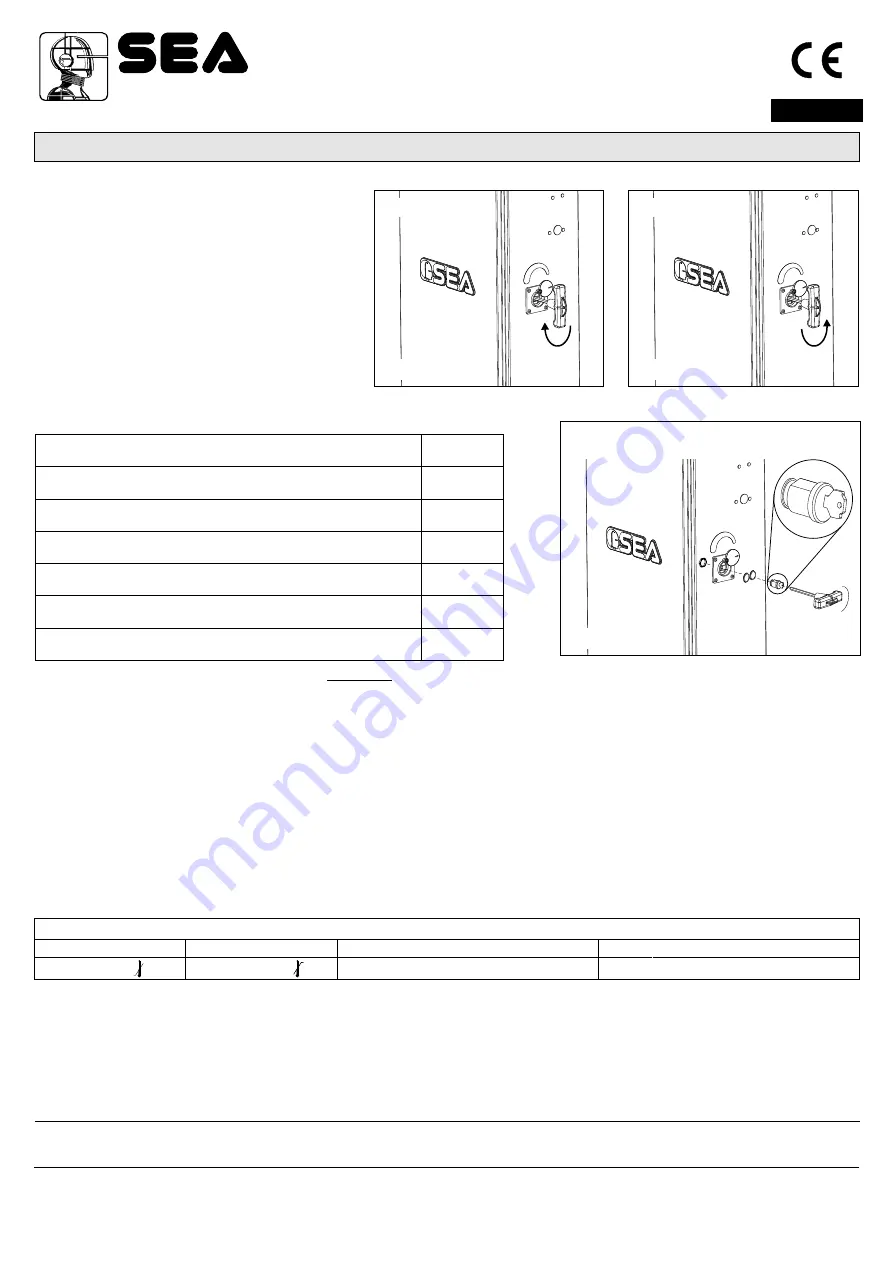
11) Release system
To release operate as follows
- Turn the protection cap of the release.
-
Insert the
and turn it about 180° into
clockwise direction until the beam is released (Fig.
12).
- Open manually the beam.
To re-lock operate as follows
- Turn the
into anti-clockwise direction
(Fig. 13).
- Extract the key.
- Re-close the protection cap.
T shaped key
T shaped key
PERIODICAL MAINTENANCE
All above mentioned operations must be executed exclusively by authorized installers.
Check the functionality of the release
Lubricate the bearing of the balance
Check the efficiency of the spring
Check the beam fixing screws and the balance and the casing
Check the integrity of the connexion cables
Check the efficiency of the batteries (where included)
Check and eventually adjust the value of intervention of the
anti-crash sensor.
Annually
Annually
Annually
Annually
Annually
Annually
Annually
To the attention of users and technicians
180°
Fig.12
180°
Fig.13
Release
Lock
19
R
(OPTIONAL)
elease key with extractable cylinder
Release
Cod. 67411465 Rev.00 - 12/2012
Fig.14


